Next: Numerical Solution of Layer Up: Error-Field Penetration in Tokamak Previous: Torque Balance Contents
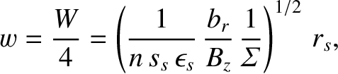
 is the critical value of the normalized error-field coil current needed to trigger error-field
penetration then the critical radial magnetic field (in the absence of a shielding current) that must be generated at the
rational surface in order to trigger penetration is
is the critical value of the normalized error-field coil current needed to trigger error-field
penetration then the critical radial magnetic field (in the absence of a shielding current) that must be generated at the
rational surface in order to trigger penetration is
![$\displaystyle \left(\frac{b_r}{B_z}\right)_{pen} = \frac{2\,m\,s_s}{(-{\mit\Del...
...}\right)\right]^{-1/2}\left(\frac{P_\varphi}{S}\right)^{1/2}\tilde{I}_{c\,pen}.$](img2595.png) |
(7.43) |
![$\displaystyle {\mit\Sigma}(Q_E) = \frac{\left([\zeta+\skew{6}\hat{\mit\Delta}_r(Q_E)]^2
+ [\skew{6}\hat{\mit\Delta}_i(Q_E)]\right)^{1/2}}{\zeta}.$](img2596.png) |
(7.44) |
Figure 7.5 shows error-field penetration calculations made for a low-field tokamak fusion reactor. The
calculation parameters are  ,
,
 ,
,  ,
,
 , and
, and
 , as well as
 ,
,  , and
, and
 , and, finally,
  ,
,  ,
,
 ,
,
 ,
,  m,
m,  , and
, and  . (See Tables 2.1, 5.1, and
6.1.) The top-left panel shows shows the
critical radial magnetic field that must be induced at the rational surface (in the absence of
shielding currents) in order to trigger error-field penetration as a function of the unperturbed electron
fluid rotation frequency at the rational surface. It can be seen that diamagnetic levels of rotation (i.e.,
. (See Tables 2.1, 5.1, and
6.1.) The top-left panel shows shows the
critical radial magnetic field that must be induced at the rational surface (in the absence of
shielding currents) in order to trigger error-field penetration as a function of the unperturbed electron
fluid rotation frequency at the rational surface. It can be seen that diamagnetic levels of rotation (i.e.,
 —see Section 5.15) are sufficient to keep
 well above
  , unless the unperturbed electron fluid rotation frequency at the
rational surface,
, unless the unperturbed electron fluid rotation frequency at the
rational surface,
 , falls significantly below the electron
diamagnetic frequency,
, falls significantly below the electron
diamagnetic frequency,
 . The bottom-left panel shows the electron fluid rotation frequency at the
rational surface as a fraction of the unperturbed rotation frequency just before (solid curve) and just after (dashed curve) penetration. It can be seen that the electron
fluid rotation frequency needs to be reduced by a substantial factor (i.e., at least, a factor of two) before penetration occurs.
However, after penetration, the electron fluid rotation frequency is effectively reduced to zero.
The top-right panel shows the shielding factors just before (solid curve) and just after (dashed curve) penetration.
It can be seen that, prior to penetration, diamagnetic levels of rotation are sufficient to reduce the amount of
driven magnetic reconnection at the rational surface by factors that exceed 200 (unless the unperturbed electron fluid rotation frequency at the
resonant surface falls significantly below
the electron diamagnetic frequency). However, after penetration, there is no shielding at all at the rational surface
(i.e.,
. The bottom-left panel shows the electron fluid rotation frequency at the
rational surface as a fraction of the unperturbed rotation frequency just before (solid curve) and just after (dashed curve) penetration. It can be seen that the electron
fluid rotation frequency needs to be reduced by a substantial factor (i.e., at least, a factor of two) before penetration occurs.
However, after penetration, the electron fluid rotation frequency is effectively reduced to zero.
The top-right panel shows the shielding factors just before (solid curve) and just after (dashed curve) penetration.
It can be seen that, prior to penetration, diamagnetic levels of rotation are sufficient to reduce the amount of
driven magnetic reconnection at the rational surface by factors that exceed 200 (unless the unperturbed electron fluid rotation frequency at the
resonant surface falls significantly below
the electron diamagnetic frequency). However, after penetration, there is no shielding at all at the rational surface
(i.e.,
 ). Finally, the bottom-right panel shows the
reduced width of the locked magnetic island chain driven at the rational surface just before (solid curve) and just after (dashed curve) penetration. It can be seen that, prior to penetration, the driven island width is of order 0.5 cm, which is about the same as the linear layer width estimated in Table 6.2. It follows that using linear theory to determine the error-field penetration threshold is a reasonable approximation (recall that linear theory would be completely invalidated were the island width to become much greater than the linear layer width—see Section 5.16.) On the other hand,
after penetration, the driven island width typically exceeds 10 cm. Such a substantial island chain would significantly degrade the
energy confinement properties of the plasma [1,5], and might even trigger a disruption. It is also clear that, after penetration, the driven tearing perturbation is governed by nonlinear, rather than linear, physics.
). Finally, the bottom-right panel shows the
reduced width of the locked magnetic island chain driven at the rational surface just before (solid curve) and just after (dashed curve) penetration. It can be seen that, prior to penetration, the driven island width is of order 0.5 cm, which is about the same as the linear layer width estimated in Table 6.2. It follows that using linear theory to determine the error-field penetration threshold is a reasonable approximation (recall that linear theory would be completely invalidated were the island width to become much greater than the linear layer width—see Section 5.16.) On the other hand,
after penetration, the driven island width typically exceeds 10 cm. Such a substantial island chain would significantly degrade the
energy confinement properties of the plasma [1,5], and might even trigger a disruption. It is also clear that, after penetration, the driven tearing perturbation is governed by nonlinear, rather than linear, physics.
Figure 7.6 shows error-field penetration calculations made for a high-field tokamak fusion reactor. The
calculation parameters are
 , and
, as well as
, and
, as well as
 , , and
, and, finally, , ,
, , and
, and, finally, , ,
 ,
,
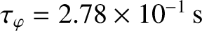 ,
,  m, , and . (See Tables 2.1, 5.1, and
6.1.) It can be seen, by comparison with Figure 5.5, that error-field penetration
in a high-field tokamak fusion reactor is fairly similar to that in a low-field reactor. The main differences are that the
shielding factors and driven island widths are somewhat smaller in the high-field case compared to the low-field case.
m, , and . (See Tables 2.1, 5.1, and
6.1.) It can be seen, by comparison with Figure 5.5, that error-field penetration
in a high-field tokamak fusion reactor is fairly similar to that in a low-field reactor. The main differences are that the
shielding factors and driven island widths are somewhat smaller in the high-field case compared to the low-field case.
![\includegraphics[width=1.\textwidth]{Chapter07/Figure7_6.eps}](img2611.png)
|