Next: Bibliography Up: Error-Field Penetration in Tokamak Previous: Error-Field Penetration Contents
 . Likewise, the high-field error-field penetration calculations shown in Figure 7.6 use the analytical
approximations (7.22) and (7.23) to determine the layer matching parameter. An alternative approach would be
to determine the layer matching parameter directly via numerical solution of the layer equations, as described in Section 5.14. The latter approach is more accurate than relying on analytic approximations, but is
also much more time consuming.
. Likewise, the high-field error-field penetration calculations shown in Figure 7.6 use the analytical
approximations (7.22) and (7.23) to determine the layer matching parameter. An alternative approach would be
to determine the layer matching parameter directly via numerical solution of the layer equations, as described in Section 5.14. The latter approach is more accurate than relying on analytic approximations, but is
also much more time consuming.
![\includegraphics[width=1.\textwidth]{Chapter07/Figure7_7.eps}](img2612.png)
|
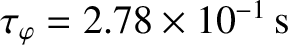
Figure 7.7 shows error-field penetration calculations
made for a low-field tokamak fusion reactor that employ numerical solutions
of the layer equations (with  , because the error-field is static), rather than analytical approximations, to determine the layer matching parameter.
The calculation parameters are
, because the error-field is static), rather than analytical approximations, to determine the layer matching parameter.
The calculation parameters are  ,
,
 ,
,  ,
,
 , and
, and
 , as well as
 ,
,  , and
, and
 , and, finally,
  ,
,  ,
,
 ,
,
 ,
,  m,
m,  , and
, and  . (See Tables 2.1, 5.1, and
6.1.) It can be seen, by comparison with Figure 7.5, that the analytical approximations (7.16) and (7.17) lead to a slight underestimate of the shielding factor prior to penetration. The calculations shown in
Figure 7.7 also exhibits a slight asymmetry between positive and negative values of the unperturbed (by the error-field) electron
fluid rotation frequency,
. (See Tables 2.1, 5.1, and
6.1.) It can be seen, by comparison with Figure 7.5, that the analytical approximations (7.16) and (7.17) lead to a slight underestimate of the shielding factor prior to penetration. The calculations shown in
Figure 7.7 also exhibits a slight asymmetry between positive and negative values of the unperturbed (by the error-field) electron
fluid rotation frequency,
 , at the rational surface that is not captured by calculations that depend on analytical
approximations. (If
, at the rational surface that is not captured by calculations that depend on analytical
approximations. (If
 then the tearing mode resonant at the rational surface would rotate in the electron diamagnetic direction were it naturally unstable. If
 then the mode would rotate in the
ion diamagnetic direction.) This asymmetry is due to ion diamagnetic flows. Nevertheless, the level of agreement between the calculations shown in Figures 7.5 and 7.7 is
sufficiently good to warrant using analytic approximations in calculations that do not require extreme accuracy.
then the mode would rotate in the
ion diamagnetic direction.) This asymmetry is due to ion diamagnetic flows. Nevertheless, the level of agreement between the calculations shown in Figures 7.5 and 7.7 is
sufficiently good to warrant using analytic approximations in calculations that do not require extreme accuracy.
![\includegraphics[width=1.\textwidth]{Chapter07/Figure7_8.eps}](img2617.png)
|
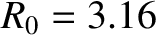
Figure 7.8 shows error-field penetration calculations
made for a high-field tokamak fusion reactor that employ numerical solutions
of the layer equations, rather than analytical approximations, to determine the layer matching parameter.
The calculation parameters are ,
 ,
,  ,
, and
, as well as
,
, and
, as well as
 , , and
, and, finally, , ,
, , and
, and, finally, , ,
 ,
,
 ,
,  m, , and . (See Tables 2.1, 5.1, and
6.1.) Again, it can be seen, by comparison with Figure 7.6, that calculations that rely on analytic
approximations lead to a slight underestimate of the shielding factor prior to penetration, and do not capture a slight asymmetry between positive and negative values of the electron
fluid rotation frequency at the rational surface.
m, , and . (See Tables 2.1, 5.1, and
6.1.) Again, it can be seen, by comparison with Figure 7.6, that calculations that rely on analytic
approximations lead to a slight underestimate of the shielding factor prior to penetration, and do not capture a slight asymmetry between positive and negative values of the electron
fluid rotation frequency at the rational surface.