Linear Pinches
Figure 1.4:
Schematic diagram of a linear pinch.
|
|
Let us examine a particularly simple magnetic confinement device. Suppose that the plasma is contained in a cylindrical vacuum vessel of radius  and finite length, capped by conducting end plates. See Figure 1.4. Let
  ,
,  ,
,  be a conventional cylindrical coordinate system whose axis corresponds to that of the vessel.
Suppose that a uniform
axial current,
be a conventional cylindrical coordinate system whose axis corresponds to that of the vessel.
Suppose that a uniform
axial current,  , is driven through the plasma by electrically biasing the end plates. In other words, suppose that the electric current density within the plasma
is
, is driven through the plasma by electrically biasing the end plates. In other words, suppose that the electric current density within the plasma
is
 |
(1.51) |
The axial current generates a “poloidal” magnetic field that circulates around the axis of the cylinder:
 |
(1.52) |
Here,
 and
and
 .
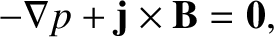
The axial current crossed with the poloidal magnetic field generates an inward radial force that compresses the plasma. This is known as the
pinch effect [40], and the type of magnetic confinement device described here is called a linear pinch (or, sometimes, a Z pinch) [26]. In equilibrium, we expect [21]
.
The axial current crossed with the poloidal magnetic field generates an inward radial force that compresses the plasma. This is known as the
pinch effect [40], and the type of magnetic confinement device described here is called a linear pinch (or, sometimes, a Z pinch) [26]. In equilibrium, we expect [21]
 |
(1.53) |
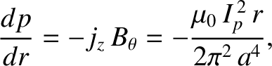
where  is the plasma pressure. Thus, we obtain
 |
(1.54) |
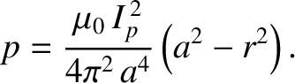
which can be integrated to give
 |
(1.55) |
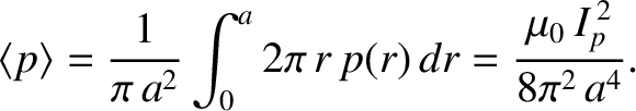
The volume-averaged pressure is
 |
(1.56) |
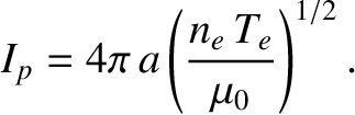
Let is make the identification [see Equation (1.22)]
 |
(1.57) |
where  and
and  are the volume-averaged electron number density and electron temperature within the plasma,
respectively.
are the volume-averaged electron number density and electron temperature within the plasma,
respectively.
Table 1.5:
More characteristic properties of a thermonuclear plasma trapped in a low-field and a high-field magnetic confinement device.
Here,  is the magnetic field-strength, the plasma current,
  the poloidal magnetic field-strength,
 the plasma
temperature due to ohmic heating alone,
the plasma
temperature due to ohmic heating alone,
 the energy loss rate per unit volume,
  the Alfvén time,
  the resistive time,
  the Lundquist number,
  the maximum thickness of the wall material that can be ablated into the plasma,
  the electron mean-free-path between collisions,
 the
parallel energy confinement time,
the
parallel energy confinement time,
 the electron energy flux into the end plates of a linear pinch, and
  the energy flux into the curved wall of a linear pinch.
| |
Low-Field |
High-Field |
 |
5.0 |
12.0 |
 |
8.9 |
8.9 |
 |
0.71 |
1.7 |
 |
0.48 |
0.48 |
 |
 |
1.5 |
 |
 |
 |
 |
 |
 |
|
 |
 |
 |
 |
 |
 |
 |
 |
 |
 |
|
 |
7.4 |
43 |
 |
 |
0.81 |
|
The previous two equations yield
 |
(1.58) |
Table 1.5 uses the information in Table 1.2 to estimate the critical plasma current needed to achieve self-sustaining
nuclear fusion. It can be seen that, in both low-field and high-field confinement devices, the critical current is about 9 MA.
The critical poloidal magnetic field-strength needed to achieve nuclear fusion is
 |
(1.59) |
Note from Table 1.5 that the critical poloidal field-strength is much less than the total field-strength. This is because another much larger component of the
magnetic field (in this case, an axial component) is needed to stabilize the plasma [26]. (See Section 1.10.)
As well as generating a poloidal magnetic field, the axial current that passes through the plasma heats it ohmically. The ohmic
heating rate per unit volume is
 |
(1.60) |
where
 |
(1.61) |
is the electrical conductivity of the plasma [21]. (See Section 2.6.) Let us investigate whether ohmic heating alone is capable of
generating a high enough plasma temperature for nuclear fusion. Now, a steady state is achieved when the ohmic heating rate balances the
energy loss rate:
 |
(1.62) |
Here,
 |
(1.63) |
where use has been made of Equations (1.11), (1.14), (1.24), and (1.58).
is estimated in Table 1.5.
The previous four equations suggest that the plasma temperature achieved by ohmic heating alone is
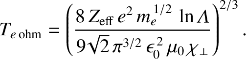 |
(1.64) |
According to Table 1.5, using
 and
and
 (see Sections 1.5 and 1.6),
is only about
0.48 keV. However, this is the volume-averaged electron temperature. If we assume that the temperature profile is peaked in the same
manner as the pressure profile in Equation (1.55) then we conclude that the central electron temperature due to ohmic heating alone is about
(see Sections 1.5 and 1.6),
is only about
0.48 keV. However, this is the volume-averaged electron temperature. If we assume that the temperature profile is peaked in the same
manner as the pressure profile in Equation (1.55) then we conclude that the central electron temperature due to ohmic heating alone is about  keV. This is still well below the plasma temperature (i.e., 7 keV) needed for self-sustaining nuclear fusion. Thus, we deduce that,
in order to achieve thermonuclear fusion in a magnetic confinement device, the plasma must be subject to additional heating. This so-called
auxiliary heating is usually provided by high-energy neutral particles, or radio-frequency electromagnetic
waves, injected into the plasma [64]. If
keV. This is still well below the plasma temperature (i.e., 7 keV) needed for self-sustaining nuclear fusion. Thus, we deduce that,
in order to achieve thermonuclear fusion in a magnetic confinement device, the plasma must be subject to additional heating. This so-called
auxiliary heating is usually provided by high-energy neutral particles, or radio-frequency electromagnetic
waves, injected into the plasma [64]. If
 is the auxiliary heating rate per unit volume then we can write
 |
(1.65) |
The previous five equations yield
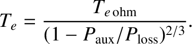 |
(1.66) |
Hence, we conclude that plasma temperatures sufficient for nuclear fusion can be achieved by means of auxiliary heating, but requires
 .
.
There are two serious problems with a linear pinch magnetic confinement device. The first problem is that the plasma is ideally unstable. A so-called ideal plasma
instability is one that does not change the topology of the magnetic field (i.e., it does not require the reconnection of magnetic field-lines). For the case of a linear
pinch, the relevant instabilities are the “sausage” mode and the “kink” mode [26]. These instabilities are global in nature, cause distortions in the shape of
the plasma that are consistent with their names, and lead to the complete disruption of the plasma discharge [50]. Ideal instabilities arise because the force balance criterion described in Equation (1.53) breaks down. Consequently,
the electromagnetic pinch force is balanced by plasma inertia, rather than by plasma pressure. In other words,
 |
(1.67) |
where  is the plasma mass density, and
  is the plasma (i.e., ion) velocity. We can make the following estimates:
 , where
is specified in Equation (1.59);
, where
is specified in Equation (1.59);
 ;
;
 ,
where
,
where
 kg and
 kg are the deuteron and triton masses, respectively;
 , where is the typical
timescale on which an ideal mode grows; and
, where is the typical
timescale on which an ideal mode grows; and
 , which is appropriate to a global instability. These estimates lead to the
following estimate for the characteristic timescale on which an ideal instability grows:
, which is appropriate to a global instability. These estimates lead to the
following estimate for the characteristic timescale on which an ideal instability grows:
 |
(1.68) |
Here, is known as the Alfvén time [26]. According to Table 1.5, the Alfvén time is of order a microsecond in a linear pinch. We conclude
that ideal instabilities would disrupt a plasma confined in a linear pinch on a timescale that is about a million times shorter than the energy confinement time needed
to achieve nuclear fusion. (See Table 1.2.) Clearly, it is imperative that a plasma in a magnetic confinement device be rendered stable to ideal instabilities.
This goal can be achieved in a linear pinch by adding an axial magnetic field,
 , whose strength greatly exceeds that of the poloidal field [26].
The second problem with a linear pinch is associated with the need to keep the impurity content of the plasma within acceptable limits. Suppose, for the
sake of example, that the inner surface of the vacuum vessel is lined with graphite tiles, as is the case in many magnetic confinement devices. The mass density of
graphite is
 . Moreover, the mass of a carbon atom is
 kg. Thus, the number density of
carbon atoms within the tiles is
kg. Thus, the number density of
carbon atoms within the tiles is
 . Note that this number density exceeds that of the particles in the plasma
by nine orders of magnitude. (See Table 1.2.) Now, we need to keep the impurity content of the plasma such that
. Note that this number density exceeds that of the particles in the plasma
by nine orders of magnitude. (See Table 1.2.) Now, we need to keep the impurity content of the plasma such that
 , otherwise
the fuel ion dilution and radiation losses become unacceptable. According to Table 1.3, this implies that the number density of carbon atoms within the plasma,
, otherwise
the fuel ion dilution and radiation losses become unacceptable. According to Table 1.3, this implies that the number density of carbon atoms within the plasma,  , cannot
exceed 1.5% of the electron number density. Suppose that, as a consequence of plasma-wall interaction, a layer of carbon atoms of thickness is
ablated into the plasma. It is easily demonstrated that
, cannot
exceed 1.5% of the electron number density. Suppose that, as a consequence of plasma-wall interaction, a layer of carbon atoms of thickness is
ablated into the plasma. It is easily demonstrated that
 |
(1.69) |
which yields
 |
(1.70) |
It can be seen from Table 1.5 that
 m, which is about 10 times smaller than the interatomic spacing of carbon atoms in graphite. Thus, we
conclude that, in order to avoid unacceptable fuel ion dilution and radiation losses, plasma-wall interactions must result in less than an atomic monolayer of the plasma-facing components ending up in the plasma. Obviously, this is a very stringent criterion. If the inner surface of the vacuum vessel is lined with tungsten, instead of carbon, then the criterion becomes
even more stringent. In fact, only about 1 tungsten atom in 1000 making up the first atomic monolayer of the plasma-facing components can end up in the plasma.
m, which is about 10 times smaller than the interatomic spacing of carbon atoms in graphite. Thus, we
conclude that, in order to avoid unacceptable fuel ion dilution and radiation losses, plasma-wall interactions must result in less than an atomic monolayer of the plasma-facing components ending up in the plasma. Obviously, this is a very stringent criterion. If the inner surface of the vacuum vessel is lined with tungsten, instead of carbon, then the criterion becomes
even more stringent. In fact, only about 1 tungsten atom in 1000 making up the first atomic monolayer of the plasma-facing components can end up in the plasma.
In a linear pinch, the interaction of the plasma with the curved surface of the vacuum vessel is moderated by
the small gyro-radii of charged particles within the plasma, which ensure that particles cannot freely stream to the surface, but instead have to slowly diffuse across
magnetic field-lines in order to reach it. (See Section 2.6.) However, in the presence of an axial magnetic field, charged particles can reach the end plates by moving along magnetic
field-lines. This process is not moderated by the small particle gyro-radii. In fact, the only possible moderation mechanism is collisions. The mean-free-path between collisions of an
electron moving parallel to a magnetic field-line is [21]
 |
(1.71) |
where
 is the electron thermal velocity, and
 |
(1.72) |
is the electron-ion collision time [21]. (See Section 2.4.) According to Table 1.5, the electron mean-free-path between collisions is of order a kilometer. The ion mean-free-path
between collisions is of similar magnitude. (See Table 2.1. Note that is calculated with
 in this table.) Given that a kilometer is very much longer than the conceivable length of a practical linear pinch, we conclude that collisions do
not moderate the flow of charged particles along magnetic field-lines to the end plates at all. In other words, electron and ion thermal energy effectively
flows along magnetic field-lines to the end plates at the appropriate thermal velocity. Suppose that the pinch has a length of
in this table.) Given that a kilometer is very much longer than the conceivable length of a practical linear pinch, we conclude that collisions do
not moderate the flow of charged particles along magnetic field-lines to the end plates at all. In other words, electron and ion thermal energy effectively
flows along magnetic field-lines to the end plates at the appropriate thermal velocity. Suppose that the pinch has a length of  m. Electron thermal energy that flows along
magnetic field-lines to the end plates is effectively only confined within the plasma for a time
m. Electron thermal energy that flows along
magnetic field-lines to the end plates is effectively only confined within the plasma for a time
 |
(1.73) |
As shown in Table 1.5,
this parallel energy confinement time is less than a microsecond, which means that it is at least a million times too small for the purposes of nuclear fusion. (See Table 1.2.)
The flux of electron thermal energy into the end plates is
 |
(1.74) |
As shown in Table 1.5, this flux is of order a terawatt per meter squared. Obviously, it is impossible to believe that ablation at a solid surface subject to such an enormous energy flux
could be limited to a monolayer, or less, of atoms.
By contrast, the flux of plasma thermal energy into the curved wall is
 |
(1.75) |
As shown in Table 1.5, this flux is much more manageable, being less than a megawatt per meter squared.
![\includegraphics[width=0.8\textwidth]{Chapter01/Figure1_4.eps}](img322.png)