Next: Alternating Current Circuits Up: Magnetic Induction Previous: Motional Emf
Let  be the length of the coil along its axis of rotation, and
  the
width of the coil perpendicular to this axis. Suppose that the
coil rotates at constant angular velocity
the
width of the coil perpendicular to this axis. Suppose that the
coil rotates at constant angular velocity  in a uniform
magnetic field of strength
in a uniform
magnetic field of strength  . The velocity
  with which the two
long sides of the coil (i.e.,
sides
with which the two
long sides of the coil (i.e.,
sides  and
and  ) move through the magnetic field is simply the product
of the angular velocity of rotation and the distance
) move through the magnetic field is simply the product
of the angular velocity of rotation and the distance  of each
side from the axis of rotation, so
of each
side from the axis of rotation, so
 . The motional emf
induced in each side is given by
. The motional emf
induced in each side is given by
 , where
  is
the component of the magnetic field perpendicular to instantaneous direction
of motion of the side in question.
If the direction of the magnetic field subtends an
angle
is
the component of the magnetic field perpendicular to instantaneous direction
of motion of the side in question.
If the direction of the magnetic field subtends an
angle  with the normal direction to
the coil, as shown in the figure, then
with the normal direction to
the coil, as shown in the figure, then
 .
Thus, the magnitude of the motional emf generated in sides and
is
.
Thus, the magnitude of the motional emf generated in sides and
is
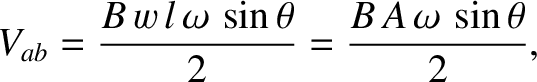 |
(2.402) |
 is the area of the coil.
The emf is zero when
is the area of the coil.
The emf is zero when
 or
or  , because the
direction of motion of sides and is parallel to the direction
of the magnetic field in these cases. The emf attains its maximum value when
, because the
direction of motion of sides and is parallel to the direction
of the magnetic field in these cases. The emf attains its maximum value when
 or
or  , because the direction of motion of
sides and is perpendicular to the direction of the magnetic field
in these cases. Incidentally, it is clear, from symmetry, that no net motional
emf is generated in sides
, because the direction of motion of
sides and is perpendicular to the direction of the magnetic field
in these cases. Incidentally, it is clear, from symmetry, that no net motional
emf is generated in sides  and
and  of the coil.
Suppose that the direction of rotation of the coil is such that side
is moving into the page in Figure 2.32 (side view), whereas side
is moving out of the page. The motional emf induced in side acts from
 to
to  . Likewise, the motional
emf induce in side acts from
. Likewise, the motional
emf induce in side acts from  to
to  . It can be seen that both emfs
act in the clockwise direction around the coil. [The direction of the emf is the same as the direction of the
electric field seen in the rest frame of the sides. See Equation (2.401).] Thus, the net emf
. It can be seen that both emfs
act in the clockwise direction around the coil. [The direction of the emf is the same as the direction of the
electric field seen in the rest frame of the sides. See Equation (2.401).] Thus, the net emf
 acting around the
coil is
acting around the
coil is  . If the coil has
  turns then the net emf becomes
 . Hence, the general expression for the emf generated around a
steadily-rotating, multi-turn coil in a uniform magnetic field is
. Hence, the general expression for the emf generated around a
steadily-rotating, multi-turn coil in a uniform magnetic field is
 for a steadily rotating coil (assuming that
 at
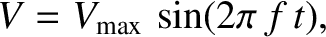
at  ). This expression can also be written
where
is the peak emf produced by the generator, and
). This expression can also be written
where
is the peak emf produced by the generator, and
 is the number of complete rotations the coils executes per second. Thus, the
peak emf is directly proportional to the area of the coil, the number of turns
in the coil, the rotation frequency of the coil,
and the magnetic field-strength.
is the number of complete rotations the coils executes per second. Thus, the
peak emf is directly proportional to the area of the coil, the number of turns
in the coil, the rotation frequency of the coil,
and the magnetic field-strength.
Figure 2.33 shows the emf specified in Equation (2.404) plotted as a function
of time. It can be seen that the variation of the emf with time is
sinusoidal in nature. The emf attains its peak values when the plane of
the coil is parallel to the plane of the magnetic field, passes through
zero when the plane of the coil is perpendicular to the magnetic field, and reverses
sign every half period of revolution of the coil. The emf is periodic
(i.e., it continually repeats the same pattern in time), with
period  (which is, of course, the rotation period of the coil).
Suppose that some electrical load (e.g., a light-bulb, or an electric heating
element) of resistance  is connected across the terminals of the
generator. In practice, this is achieved by connecting the two ends of the
coil to rotating rings that are then connected to the external circuit by means
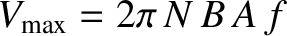
of metal brushes. According to Ohm's law, the current
is connected across the terminals of the
generator. In practice, this is achieved by connecting the two ends of the
coil to rotating rings that are then connected to the external circuit by means
of metal brushes. According to Ohm's law, the current  that flows in the
load is given by
that flows in the
load is given by
 , generator.
The current that flows through the load must also flow around the coil.
Because the coil is situated in a magnetic field, this current gives rise to
a torque acting on the coil which, as is easily demonstrated, acts to slow down its
rotation. Suppose, as before, that side
is moving into the page in Figure 2.32 (side view), whereas side
is moving out of the page, and the current is circulating in a clockwise sense.
Side experiences a magnetic force per unit length
 that acts to
oppose its motion. (See Section 2.2.2.)
Hence, the braking force acting on the side is
that acts to
oppose its motion. (See Section 2.2.2.)
Hence, the braking force acting on the side is
 . Thus, the braking torque acting on the
side is
. Thus, the braking torque acting on the
side is
 , where
  is the area of the coil.
Side experiences an equal torque.
So, taking into account the fact that the coils has turns, the net braking torque
is the area of the coil.
Side experiences an equal torque.
So, taking into account the fact that the coils has turns, the net braking torque  acting
on the coil is given by
acting
on the coil is given by
 |
(2.407) |
 .
An external
torque that is equal and opposite to the breaking torque must be applied to
the coil if it is to rotate uniformly, as was initially assumed
above. The rate
.
An external
torque that is equal and opposite to the breaking torque must be applied to
the coil if it is to rotate uniformly, as was initially assumed
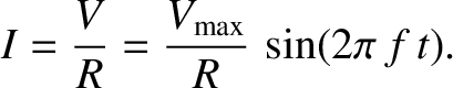
above. The rate  at which this external torque does work is equal to the
product of the torque and the angular velocity of the coil. (See Section 1.7.4.) Thus,
at which this external torque does work is equal to the
product of the torque and the angular velocity of the coil. (See Section 1.7.4.) Thus,
 |
(2.409) |
 at which electrical energy is generated in the circuit comprising the rotating coil and the load.
Equations (2.403), (2.406), and (2.408) yield
where . Figure 2.34 shows the braking
torque plotted as a function of time
. Figure 2.34 shows the braking
torque plotted as a function of time  , according to
Equation (2.410). It can be seen that the
torque is always of the same sign (i.e., it always acts in the same
direction, so as to continually oppose the
rotation of the coil), but is not constant
in time. Instead, it pulsates periodically with period
, according to
Equation (2.410). It can be seen that the
torque is always of the same sign (i.e., it always acts in the same
direction, so as to continually oppose the
rotation of the coil), but is not constant
in time. Instead, it pulsates periodically with period  . The braking
torque attains its maximum value whenever the plane of the coil is parallel to the
plane of the magnetic field, and is zero whenever the plane of the coil is perpendicular
to the magnetic field. It is clear that the external torque needed
to keep the coil rotating at a constant angular velocity must also pulsate
in time with period . A constant external torque would give rise to a non-uniformly rotating
coil, and, hence, to an alternating emf that varies with time in a more
complicated manner than
. The braking
torque attains its maximum value whenever the plane of the coil is parallel to the
plane of the magnetic field, and is zero whenever the plane of the coil is perpendicular
to the magnetic field. It is clear that the external torque needed
to keep the coil rotating at a constant angular velocity must also pulsate
in time with period . A constant external torque would give rise to a non-uniformly rotating
coil, and, hence, to an alternating emf that varies with time in a more
complicated manner than
 .
.
Virtually all commercial power stations generate electricity using AC generators.
The external power needed to turn the generating coil is usually supplied by
a steam turbine (steam blasting against fan-like blades that are
forced into rotation). Water is vaporized to produce
high pressure
steam by burning coal, or by using the energy released inside a nuclear
reactor.
Of course, in hydroelectric power stations, the power needed
to turn the generator coil is supplied by a water turbine (which is similar
to a steam turbine, except that falling water plays the role of the steam).
More recently, a new type of power station has been developed in which the
power needed to rotate the generating coil is supplied by a gas turbine
(basically, a large jet engine that burns natural gas). In the U.S.
and Canada, the alternating electrical signal generated by power stations and fed into ordinary households, which is known as mains electricity, oscillates at
 Hz, which implies that the
generator coils in power stations rotate exactly
sixty times a second. In Europe and Asia, the oscillation frequency
of mains electricity is
Hz, which implies that the
generator coils in power stations rotate exactly
sixty times a second. In Europe and Asia, the oscillation frequency
of mains electricity is  Hz.
Hz.
![\includegraphics[height=3in]{Chapter03/fig9_05.eps}](img1902.png)
![\includegraphics[height=2.25in]{Chapter03/fig9_06.eps}](img1921.png)
![\includegraphics[height=2.5in]{Chapter03/fig9_07.eps}](img1935.png)