Next: Ampère's Law Up: Magnetostatic Fields Previous: Magnetism
Consider an experiment in which a long straight wire carries an
electrical
current  . As is easily demonstrated, the needle of a small compass maps
out a series of concentric circular loops in the plane
perpendicular to such a wire. See Figure 2.13.
The direction of circulation around such magnetic loops is conventionally taken to be
the direction in which the north pole of a compass needle
points.
Using this convention, the circulation of the loops is given by a
right-hand rule. If the thumb of the right-hand points along the direction of the
current then the fingers of the right-hand circulate in the same sense as the
magnetic loops.
. As is easily demonstrated, the needle of a small compass maps
out a series of concentric circular loops in the plane
perpendicular to such a wire. See Figure 2.13.
The direction of circulation around such magnetic loops is conventionally taken to be
the direction in which the north pole of a compass needle
points.
Using this convention, the circulation of the loops is given by a
right-hand rule. If the thumb of the right-hand points along the direction of the
current then the fingers of the right-hand circulate in the same sense as the
magnetic loops.
Our next experiment involves bringing a short test wire, carrying
a current  ,
close to the original long straight wire, and investigating the force exerted on the test wire.
This experiment is not quite as clear cut as Coulomb's experiment regarding the force exerted between electric charges, because, unlike
electric charges,
electric currents cannot exist as point entities; they
have to flow in complete circuits. We must
imagine that the circuit that connects with the central wire is sufficiently
far away that it has no appreciable influence on the outcome of the experiment.
The circuit that connects with
the test wire is more problematic. Fortunately, if the
feed wires are twisted around each other, as indicated in Figure 2.14, then
they effectively cancel one another out, and also do not influence the outcome of
the experiment.
,
close to the original long straight wire, and investigating the force exerted on the test wire.
This experiment is not quite as clear cut as Coulomb's experiment regarding the force exerted between electric charges, because, unlike
electric charges,
electric currents cannot exist as point entities; they
have to flow in complete circuits. We must
imagine that the circuit that connects with the central wire is sufficiently
far away that it has no appreciable influence on the outcome of the experiment.
The circuit that connects with
the test wire is more problematic. Fortunately, if the
feed wires are twisted around each other, as indicated in Figure 2.14, then
they effectively cancel one another out, and also do not influence the outcome of
the experiment.
It can easily be demonstrated that the force exerted on the test wire is directly proportional
to its length. Furthermore,
if the current in the test wire
(i.e., the test current) flows parallel to the current in the central wire
then the two wires attract one another. If the current in the test
wire is reversed then the two wires repel one another.
If the test current is directed radially toward the central wire
(and the current in the central wire flows upward) then the test wire
is subject to a downward force. If the test current is reversed then the force is
upward. If the test current is rotated in a single plane, such that it starts
parallel to the central current and ends up pointing radially
toward it, then the force on
the test wire is of constant magnitude, and is always perpendicular to the
test current. If the test current is parallel to a magnetic loop then there is
no force exerted on the test wire. If the test current is rotated in
a single plane, such that it starts parallel to the central current, and ends up
pointing along a magnetic loop, then the magnitude of the force on the
test wire attenuates like
 (where
  is the angle through which the current
is turned, and
is the angle through which the current
is turned, and  corresponds to the
case where the test current is parallel to the central current),
and its direction is again always perpendicular to
the test current. Finally, the attractive
force between two parallel current-carrying wires is proportional to the product of
the two currents, and
inversely proportional to the perpendicular
distance between the wires.
corresponds to the
case where the test current is parallel to the central current),
and its direction is again always perpendicular to
the test current. Finally, the attractive
force between two parallel current-carrying wires is proportional to the product of
the two currents, and
inversely proportional to the perpendicular
distance between the wires.
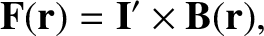
The rather complicated force law established by the previously described experiments can be summed up succinctly provided that we define a vector field
 , called the magnetic field,
that fills space, and
whose direction is everywhere tangential to the
magnetic loops mapped out by the north
pole of a small
compass. The dependence of the force per unit length,
, called the magnetic field,
that fills space, and
whose direction is everywhere tangential to the
magnetic loops mapped out by the north
pole of a small
compass. The dependence of the force per unit length,  , acting on a
test wire, located at displacement
, acting on a
test wire, located at displacement  , with the different
possible orientations of the test current is described by
, with the different
possible orientations of the test current is described by
 is a vector whose direction and magnitude are the same as those
of the test current.
is a vector whose direction and magnitude are the same as those
of the test current.
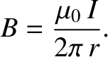
The variation of the force per unit length acting on
a test wire with the strength of the
central current, , and the perpendicular distance,  , to the central wire, is
accounted for by saying that the strength of the magnetic generated around the central wire is directly proportional to , and
inversely proportional to . Thus, we can write
, to the central wire, is
accounted for by saying that the strength of the magnetic generated around the central wire is directly proportional to , and
inversely proportional to . Thus, we can write
 is called the
magnetic permeability of free space, and takes the value
is called the
magnetic permeability of free space, and takes the value
 |
(2.207) |
The concept of a magnetic field that fills the space around a current-carrying wire allows the calculation of the force on a test wire to be conveniently split into two parts. In the first part, we calculate the magnetic field generated by the current flowing in the central wire. This field circulates in the plane normal to the wire. Its magnitude is proportional to the central current, and inversely proportional to the perpendicular distance from the wire. In the second part, we employ Equation (2.205) to calculate the force per unit length acting on a short current-carrying wire placed in the magnetic field generated by the central current. This force is perpendicular to both the direction of the magnetic field and the direction of the test current. Note that, at this stage, we have no reason to suppose that the magnetic field has any real existence; it is introduced merely to facilitate the calculation of the force exerted on the test wire by the central wire.
![\includegraphics[height=2.5in]{Chapter03/fig8_01.eps}](img1502.png)
![\includegraphics[height=2.5in]{Chapter03/fig8_02.eps}](img1504.png)