Mutual Inductance
Consider two long, thin, cylindrical solenoids, one wound on top of the other. The common length
of each solenoid is  , and the common radius is
  . Suppose that the inner
solenoid has
. Suppose that the inner
solenoid has  turns per unit length, and carries a current
  . The magnetic field generated within the inner
solenoid is
. The magnetic field generated within the inner
solenoid is
 . [See Equation (2.322).] The magnetic
flux passing through each turn of the outer solenoid is
. [See Equation (2.322).] The magnetic
flux passing through each turn of the outer solenoid is
 , and
the total flux linking the outer solenoid is therefore
, and
the total flux linking the outer solenoid is therefore
 , where
  is the number of turns per unit length of the outer
solenoid. It follows that the mutual inductance of the two solenoids, defined
is the number of turns per unit length of the outer
solenoid. It follows that the mutual inductance of the two solenoids, defined
 [see Equation (2.313)] is given by
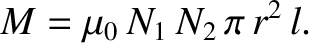 |
(2.342) |
Recall that the self inductance of the inner solenoid is
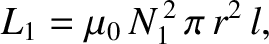 |
(2.343) |
and that of the outer solenoid is
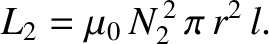 |
(2.344) |
[See Equation (2.324).]
Hence, the mutual inductance can be written
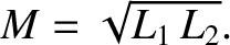 |
(2.345) |
Note that this result depends on the assumption that all of the magnetic flux produced
by one solenoid passes through the other solenoid. In reality, some of the flux
leaks out, so that the mutual inductance is somewhat less than that given in the
previous formula. We can write
 |
(2.346) |
where the dimensionless constant  is called the coefficient of coupling,
and lies in the range
is called the coefficient of coupling,
and lies in the range
 .
.
Suppose that the inner and outer solenoids have resistances  and
and  , respectively, If an instantaneous current flow through the inner solenoid then the voltage drop across it due to its resistance is
  . The voltage drop
due to the back-emf generated by the self inductance of the solenoid is
. The voltage drop
due to the back-emf generated by the self inductance of the solenoid is
 . (See Section 2.3.5.) There is also a back-emf due to inductive coupling with
the outer solenoid. The magnetic flux through the inner solenoid due to the instantaneous
current
. (See Section 2.3.5.) There is also a back-emf due to inductive coupling with
the outer solenoid. The magnetic flux through the inner solenoid due to the instantaneous
current  flowing through the outer solenoid is
 |
(2.347) |
Thus, by Faraday's law and Lenz's law, the back-emf induced in the inner solenoid is
 |
(2.348) |
[See Equation (2.284).]
The voltage drop across the inner solenoid due to its mutual inductance with the
top coil is minus this expression. Thus, the net voltage drop across the inner solenoid is
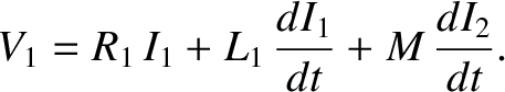 |
(2.349) |
Likewise, the net voltage drop across the outer solenoid is
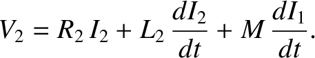 |
(2.350) |
Suppose that, at time  , we suddenly connect a battery of constant voltage
 to the inner solenoid. The outer solenoid is assumed to be
open-circuited, or connected to a voltmeter of very high internal resistance,
so that
to the inner solenoid. The outer solenoid is assumed to be
open-circuited, or connected to a voltmeter of very high internal resistance,
so that  .
Because , the circuit equation for the inner solenoid is
.
Because , the circuit equation for the inner solenoid is
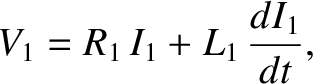 |
(2.351) |
where is constant, and
 . We have already seen the solution to
this equation:
. We have already seen the solution to
this equation:
![$\displaystyle I_1 = \frac{V_1}{R_1} \left[ 1 - \exp\left(-\frac{R_1\, t}{L_1}\right)\right].$](img1815.png) |
(2.352) |
[See Equation (2.329).]
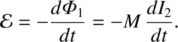
The circuit equation for the outer solenoid is
 |
(2.353) |
giving
 |
(2.354) |
It follows from Equation (2.346) that
 |
(2.355) |
Because
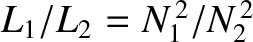 [see Equations (2.343) and (2.344)], we obtain
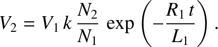 |
(2.356) |
Now,
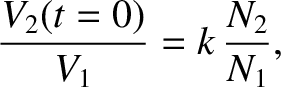 |
(2.357) |
so if
 then the voltage in the inner solenoid is considerably amplified
in the outer solenoid. This effect is the basis for old-fashioned car ignition
systems. A large voltage spike is induced in a secondary circuit (connected to
a coil with very many turns) whenever the current in a primary circuit
(connected to a coil with not so many turns) is either switched on or off.
The primary circuit is connected to the car battery (whose voltage is
typically 12 volts).
The switching is done by a set of points, which are mechanically opened and
closed as the engine turns. The large voltage spike induced in the secondary circuit,
as the points are either opened or closed, causes a spark to jump across a gap
in this circuit. This spark ignites a petrol/air mixture in one of the engine's cylinders.
We might think that the optimum configuration is to have only one turn in the primary
circuit, and many turns in the secondary circuit, so that the ratio
then the voltage in the inner solenoid is considerably amplified
in the outer solenoid. This effect is the basis for old-fashioned car ignition
systems. A large voltage spike is induced in a secondary circuit (connected to
a coil with very many turns) whenever the current in a primary circuit
(connected to a coil with not so many turns) is either switched on or off.
The primary circuit is connected to the car battery (whose voltage is
typically 12 volts).
The switching is done by a set of points, which are mechanically opened and
closed as the engine turns. The large voltage spike induced in the secondary circuit,
as the points are either opened or closed, causes a spark to jump across a gap
in this circuit. This spark ignites a petrol/air mixture in one of the engine's cylinders.
We might think that the optimum configuration is to have only one turn in the primary
circuit, and many turns in the secondary circuit, so that the ratio
 is made as large as possible. However, this is not the case. Most of
the magnetic flux generated by a single-turn primary coil is likely to
miss the secondary coil altogether. This implies that the coefficient of coupling
is small, which reduces the voltage induced in the secondary circuit. Thus, we
need a reasonable number of turns in the primary coil in order to localize the
induced magnetic flux, so that it links effectively with the secondary coil.
is made as large as possible. However, this is not the case. Most of
the magnetic flux generated by a single-turn primary coil is likely to
miss the secondary coil altogether. This implies that the coefficient of coupling
is small, which reduces the voltage induced in the secondary circuit. Thus, we
need a reasonable number of turns in the primary coil in order to localize the
induced magnetic flux, so that it links effectively with the secondary coil.