Next: Mutual Inductance Up: Magnetic Induction Previous: Self Inductance
 Circuits
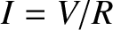
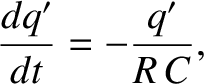
Consider a circuit in which a battery of emf  is connected in series with
a capacitor of capacitance
is connected in series with
a capacitor of capacitance  , and a resistor of resistance
  .
For fairly obvious reasons, such a circuit is generally referred to as
an circuit. In a steady state, the charge on the positive plate
of the capacitor is given by
.
For fairly obvious reasons, such a circuit is generally referred to as
an circuit. In a steady state, the charge on the positive plate
of the capacitor is given by  , and zero current flows around the circuit
(because current cannot flow across the insulating gap between the capacitor
plates).
, and zero current flows around the circuit
(because current cannot flow across the insulating gap between the capacitor
plates).
Let us now introduce a switch into the circuit, as shown in Figure 2.29. Suppose
that the switch is initially open, but is suddenly closed at  . It is
assumed that the capacitor plates are uncharged when the switch is thrown.
We expect a transient current,
. It is
assumed that the capacitor plates are uncharged when the switch is thrown.
We expect a transient current,  , to flow around the circuit until
the charge,
, to flow around the circuit until
the charge,  , on the positive plate of the capacitor attains its
final steady-state value, . But, how long does this process take?
, on the positive plate of the capacitor attains its
final steady-state value, . But, how long does this process take?
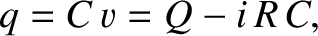
The potential difference,  , between the positive and negative plates
of the capacitor is given by
, between the positive and negative plates
of the capacitor is given by
 |
(2.331) |
, on the positive plate of the capacitor is written
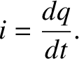
where is the final charge. Now, if is the instantaneous current
flowing around the circuit then, in a short time interval  , the
charge on the positive plate of the capacitor increases by a
small amount
, the
charge on the positive plate of the capacitor increases by a
small amount
 (because all of the charge
that flows around the circuit must accumulate on the plates of the
capacitor). It follows that
Thus, the instantaneous current flowing around the circuit is
numerically equal to the rate at which the charge accumulated
on the positive plate of
the capacitor increases with time. Equations (2.332) and
(2.333) can be combined together to give
where
At , just after the switch is closed, the charge on the positive
plate of the capacitor is zero, so
(because all of the charge
that flows around the circuit must accumulate on the plates of the
capacitor). It follows that
Thus, the instantaneous current flowing around the circuit is
numerically equal to the rate at which the charge accumulated
on the positive plate of
the capacitor increases with time. Equations (2.332) and
(2.333) can be combined together to give
where
At , just after the switch is closed, the charge on the positive
plate of the capacitor is zero, so
Integration of Equation (2.334), subject to the initial condition (2.336), yields
It follows from Equation (2.335) that![$\displaystyle q(t) = Q\left[1- \exp\left(-\frac{t}{R\,C}\right)\right]$](img1782.png) |
(2.338) |
, on the positive plate of
the capacitor a time interval,  , after the switch is closed
(at time ). The variation of the charge with time is
sketched in Figure 2.30.
It can be seen that, when the switch is closed, the charge on the
positive plate of the capacitor
does not suddenly jump up to its final value, . Instead, the charge
increases smoothly from zero, and gradually asymptotes to its final value.
The charge has risen to approximately
, after the switch is closed
(at time ). The variation of the charge with time is
sketched in Figure 2.30.
It can be seen that, when the switch is closed, the charge on the
positive plate of the capacitor
does not suddenly jump up to its final value, . Instead, the charge
increases smoothly from zero, and gradually asymptotes to its final value.
The charge has risen to approximately  of its final value a
time
of its final value a
time
 |
(2.339) |
 , the charge has risen to
more than
, the charge has risen to
more than  of its final value. Thus,
  is a good measure of
how long after the
switch is closed it takes for the capacitor to fully charge up.
The quantity
is a good measure of
how long after the
switch is closed it takes for the capacitor to fully charge up.
The quantity  is termed the time constant, or, somewhat unimaginitely, the time, of the circuit.
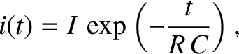
According to Equations (2.333) and (2.334),
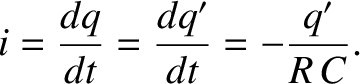 |
(2.340) |
 |
(2.341) |
 . The previous expression specifies the current, , flowing
around the circuit a time interval, , after the switch is closed
(at time ). It can be seen that, immediately after the switch is
thrown, the current, , that flows in the circuit is that which would
flow if the capacitor were replaced by a conducting wire. However, this
current is only transient, and rapidly decays away to a negligible value.
After one time, the current has decayed to 37% of its initial value.
After five times, the current has decayed to less than 1% of its initial
value. It is interesting to note that, for a short instant of time,
just after the
switch is closed, the current in the circuit acts as if there is no insulating
gap between the capacitor plates. It essentially takes an time for the
information about the break in the
circuit to propagate around the circuit, and cause the current to stop
flowing.
. The previous expression specifies the current, , flowing
around the circuit a time interval, , after the switch is closed
(at time ). It can be seen that, immediately after the switch is
thrown, the current, , that flows in the circuit is that which would
flow if the capacitor were replaced by a conducting wire. However, this
current is only transient, and rapidly decays away to a negligible value.
After one time, the current has decayed to 37% of its initial value.
After five times, the current has decayed to less than 1% of its initial
value. It is interesting to note that, for a short instant of time,
just after the
switch is closed, the current in the circuit acts as if there is no insulating
gap between the capacitor plates. It essentially takes an time for the
information about the break in the
circuit to propagate around the circuit, and cause the current to stop
flowing.
![\includegraphics[height=2in]{Chapter03/fig10_4.eps}](img1772.png)
![\includegraphics[height=2.5in]{Chapter03/fig10_6.eps}](img1787.png)