Next: Transformers Up: Magnetic Induction Previous: Alternating Current Circuits
An AC electric motor consists of the same basic elements as an
AC electric generator; that is, a multi-turn coil that is free
to rotate in a constant magnetic field.
Furthermore, the rotating coil is connected to the
external circuit in just the same manner as in an AC generator; that is, via two
slip-rings attached to metal brushes. Suppose that an external voltage
source of emf  is connected across the motor. It is assumed that
is an alternating emf, so that
is connected across the motor. It is assumed that
is an alternating emf, so that
 |
(2.433) |
 is the peak voltage, and
  is the alternation frequency.
Such an emf could be obtained from mains electricity. In this case,
is the alternation frequency.
Such an emf could be obtained from mains electricity. In this case,
 V
and
V
and  Hz in the U.S. and Canada, whereas
 V and
V and
 Hz in Europe and Asia. The external emf drives an alternating current
 |
(2.434) |
. Now a coil rotating in a magnetic field generates an emf,  .
It is easily demonstrated that this emf acts to oppose the circulation of the
current around the coil; that is, the induced emf acts in the opposite
direction to the external emf. For an
.
It is easily demonstrated that this emf acts to oppose the circulation of the
current around the coil; that is, the induced emf acts in the opposite
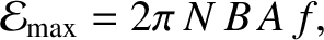
direction to the external emf. For an  -turn coil of cross-sectional area
  rotating with frequency in a magnetic field
  , the back-emf, ,
is given by
, the back-emf, ,
is given by
 |
(2.435) |
Figure 2.37 shows the circuit in question. A circle with a
wavy line inside is the conventional way of indicating an AC voltage source.
The motor is modeled as a resistor  , that represents the internal
resistance of the motor, in series with the back-emf, . Of course,
the back-emf acts in the opposite direction to the external emf, .
Application of Ohm's law (see Section 2.1.11) around the circuit gives
, that represents the internal
resistance of the motor, in series with the back-emf, . Of course,
the back-emf acts in the opposite direction to the external emf, .
Application of Ohm's law (see Section 2.1.11) around the circuit gives
 |
(2.437) |
 |
(2.438) |
 |
(2.439) |
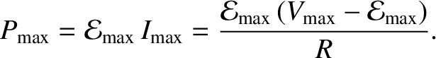
The rate  at which the motor gains electrical energy from the external
circuit is given by
at which the motor gains electrical energy from the external
circuit is given by
 |
(2.441) |
is also the rate at which the motor performs
mechanical work. Note that the rate at which the motor does mechanical
work is not constant in time, but, instead, pulsates at the rotation frequency
of the coil. It is possible to construct a motor that performs work
at a more uniform rate by employing more than one coil rotating about the
same axis.
As long as
 , the rate at which the
motor performs mechanical work is positive (i.e., the motor
does useful work). However, if
, the rate at which the
motor performs mechanical work is positive (i.e., the motor
does useful work). However, if
 then the rate at which the motor performs work becomes negative. This means that
we must perform mechanical work on the motor in order to keep it rotating, which
is another way of saying that the motor does not perform useful work.
Clearly, in order for an AC motor to perform useful work, the external emf, , must
be able to overcome the back-emf, , induced in the motor (i.e.,
).
then the rate at which the motor performs work becomes negative. This means that
we must perform mechanical work on the motor in order to keep it rotating, which
is another way of saying that the motor does not perform useful work.
Clearly, in order for an AC motor to perform useful work, the external emf, , must
be able to overcome the back-emf, , induced in the motor (i.e.,
).
![\includegraphics[height=3in]{Chapter03/fig9_10.eps}](img1985.png)