Next: Coherence Up: Wave Optics Previous: Introduction Contents
 -direction, through a transparent
dielectric medium of refractive index unity (e.g., a vacuum). (Such a wave could be produced by a uniform line
source, running parallel to the
-direction, through a transparent
dielectric medium of refractive index unity (e.g., a vacuum). (Such a wave could be produced by a uniform line
source, running parallel to the  -axis (say), that is located at
  .)
Let the associated wavefunction take the form
Here,
.)
Let the associated wavefunction take the form
Here,  represents the electric component of the wave,
  the wave amplitude,
  the
phase angle,
the
phase angle,
 the wavenumber,
 the angular frequency, and
  the velocity of light in vacuum.
Let the wave be normally incident on an opaque
screen that is coincident with the plane
the velocity of light in vacuum.
Let the wave be normally incident on an opaque
screen that is coincident with the plane  . See Figure 10.1.
Suppose that there are two identical
slits of width
. See Figure 10.1.
Suppose that there are two identical
slits of width  cut in the screen. Let the slits run parallel to the -axis, and be located at
  and
and  , where
  is the slit spacing. Suppose that the
light that passes through the two slits travels to a cylindrical projection screen of radius
is the slit spacing. Suppose that the
light that passes through the two slits travels to a cylindrical projection screen of radius  whose axis coincides with the line
  . In the
following, it is assumed that there is no variation of wave quantities in the -direction.
. In the
following, it is assumed that there is no variation of wave quantities in the -direction.
Provided the two slits are much narrower than the wavelength,
 , of the light (i.e.,
 ), we expect any radiation
that passes through them to be strongly diffracted. (See Section 10.7.) Diffraction is a fundamental wave phenomenon that
causes waves to bend around small (compared to the wavelength) obstacles, and spread out from narrow (compared to the wavelength) openings,
while maintaining the same wavelength and frequency.
The
laws of geometric optics do not take diffraction into account, and are, therefore, restricted to situations in
which light interacts with objects whose physical dimensions greatly exceed its wavelength.
The assumption of strong diffraction suggests that each slit acts like a uniform line source that emits light isotropically
in the forward direction (i.e., toward the region
), we expect any radiation
that passes through them to be strongly diffracted. (See Section 10.7.) Diffraction is a fundamental wave phenomenon that
causes waves to bend around small (compared to the wavelength) obstacles, and spread out from narrow (compared to the wavelength) openings,
while maintaining the same wavelength and frequency.
The
laws of geometric optics do not take diffraction into account, and are, therefore, restricted to situations in
which light interacts with objects whose physical dimensions greatly exceed its wavelength.
The assumption of strong diffraction suggests that each slit acts like a uniform line source that emits light isotropically
in the forward direction (i.e., toward the region  ), but does not emit light in the
backward direction (i.e., toward the region
), but does not emit light in the
backward direction (i.e., toward the region  ).
It is possible
to demonstrate that this is, in fact, the case (with certain provisos; see Section 10.10), using electromagnetic theory (Jackson 1975), but such a demonstration lies beyond the
scope of this course.
As discussed in
Section 7.4, we would expect a uniform line source to emit a cylindrical wave. It follows that each slit
emits a half-cylindrical light wave in the forward direction. See Figure 10.1. Moreover, these waves are emitted with equal amplitude and phase, because the incident
plane wave that illuminates the slits has the same amplitude (i.e.,
).
It is possible
to demonstrate that this is, in fact, the case (with certain provisos; see Section 10.10), using electromagnetic theory (Jackson 1975), but such a demonstration lies beyond the
scope of this course.
As discussed in
Section 7.4, we would expect a uniform line source to emit a cylindrical wave. It follows that each slit
emits a half-cylindrical light wave in the forward direction. See Figure 10.1. Moreover, these waves are emitted with equal amplitude and phase, because the incident
plane wave that illuminates the slits has the same amplitude (i.e.,  ) and phase (i.e.,
 ) at both slits, and the slits are identical. Finally, we expect the cylindrical waves emitted by the two slits to interfere with one
another (see Section 6.4) in such a manner as to generate a characteristic pattern on the
projection screen. Let us determine the nature of this pattern.
) at both slits, and the slits are identical. Finally, we expect the cylindrical waves emitted by the two slits to interfere with one
another (see Section 6.4) in such a manner as to generate a characteristic pattern on the
projection screen. Let us determine the nature of this pattern.
Consider the wave amplitude at a point on the projection screen that lies an angular distance  from the
plane
from the
plane  . See Figure 10.1. The wavefunction at this particular point
is written
. See Figure 10.1. The wavefunction at this particular point
is written
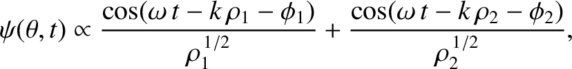
 . In other words, the overall wavefunction in the region is the superposition of cylindrical
waves [see Equation (7.11)] of equal amplitude (i.e.,
. In other words, the overall wavefunction in the region is the superposition of cylindrical
waves [see Equation (7.11)] of equal amplitude (i.e.,
 ) and phase (i.e.,
 ) emanating from each slit. Here,
 . Moreover,
  and
and  are the distances that the waves emitted by the first and second slits (located at and , respectively) have travelled by the time they reach the point on the projection screen in question.
Standard trigonometry (i.e., the law of cosines) reveals that
Likewise,![$\displaystyle \rho_2 = R\left[1+\frac{1}{2}\,\frac{d}{R}\,\sin\theta + {\cal O}\!\left(\frac{d^{\,2}}{R^{\,2}}\right)\right].$](img3271.png) |
(10.4) |
![$\cos x + \cos y\equiv 2\,\cos[(x+y)/2]\,\cos[(x-y)/2]$](img3273.png) (see Appendix B),
gives
(see Appendix B),
gives
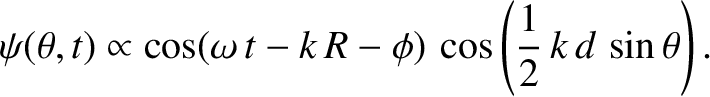
![$\displaystyle \psi(\theta,t)\propto\cos\left[\omega\,t-\frac{1}{2}\,k\,(\rho_1+...
...\right]+ {\cal O}\left(\frac{1}{k\,R}\right)+ {\cal O}\left(\frac{d}{R}\right),$](img3274.png) |
(10.6) |
![$\displaystyle \psi(\theta,t)\propto\cos\left[\omega\,t-k\,R-\phi+ {\cal O}\left...
...\right]+ {\cal O}\left(\frac{1}{k\,R}\right)+ {\cal O}\left(\frac{d}{R}\right).$](img3275.png) |
(10.7) |
![\includegraphics[width=0.9\textwidth]{Chapter10/fig10_02.eps}](img3278.png) |
The orderings (10.8), which can also be written in the form
are satisfied provided the projection screen is located sufficiently far away from the slits. Consequently, the type of interference described in this section is known as far-field interference. One characteristic feature of far-field interference is that the amplitudes of the cylindrical waves emitted by the two slits are approximately equal to one another when they reach a given point on the projection screen (i.e., ), whereas the phases are, in general, significantly different (i.e.,
 ). In other words, the
interference pattern generated on the projection screen is entirely a consequence of the phase difference between the
cylindrical waves emitted by the two slits when they reach the screen. This phase difference is produced by the slight difference in the distance between the slits and a
given point on the projection screen. (The phase difference becomes significant as soon as the path difference becomes
comparable with the wavelength of the light.)
). In other words, the
interference pattern generated on the projection screen is entirely a consequence of the phase difference between the
cylindrical waves emitted by the two slits when they reach the screen. This phase difference is produced by the slight difference in the distance between the slits and a
given point on the projection screen. (The phase difference becomes significant as soon as the path difference becomes
comparable with the wavelength of the light.)
![\includegraphics[width=0.9\textwidth]{Chapter10/fig10_03.eps}](img3282.png) |
The mean energy flux, or intensity, of the light striking the projection screen at angular position
is
 |
(10.11) |
 denotes an average over a wave period. [The previous expression follows from the standard result
 , for
an electromagnetic wave, where
, for
an electromagnetic wave, where  is the electric component of the wave, and
  the impedance of free space. (See Section 6.8.) Recall, also, that
 .] Here, use has been made of the easily established result
 .
The very high
oscillation frequency of light waves (i.e.,
.
The very high
oscillation frequency of light waves (i.e.,
 ) ensures that experiments typically detect (e.g., by
means of a photographic film, or a photo-multiplier tube) the intensity of light, rather than the rapidly
oscillating amplitude of its electric component. For the case of two-slit, far-field interference, assuming normal incidence and
narrow slits, the intensity of the characteristic interference pattern appearing
on the projection screen is specified by
) ensures that experiments typically detect (e.g., by
means of a photographic film, or a photo-multiplier tube) the intensity of light, rather than the rapidly
oscillating amplitude of its electric component. For the case of two-slit, far-field interference, assuming normal incidence and
narrow slits, the intensity of the characteristic interference pattern appearing
on the projection screen is specified by
![\includegraphics[width=0.9\textwidth]{Chapter10/fig10_04.eps}](img3289.png) |
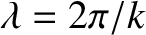
Figure 10.2 shows the intensity of the typical two-slit, far-field interference pattern produced when the slit spacing,  , greatly exceeds the wavelength,
  ,
of the light.
It can be seen that the pattern consists of multiple bright and dark fringes. A bright fringe is generated whenever the cylindrical
waves emitted by the two slits interfere constructively at a given point on the projection screen. This occurs when the distances between the
two slits and the point in question differ by an integer number of wavelengths; that is,
,
of the light.
It can be seen that the pattern consists of multiple bright and dark fringes. A bright fringe is generated whenever the cylindrical
waves emitted by the two slits interfere constructively at a given point on the projection screen. This occurs when the distances between the
two slits and the point in question differ by an integer number of wavelengths; that is,
 is an integer. (This ensures that the effective phase difference of the two waves is zero.)
Likewise, a dark fringe is generated whenever the cylindrical waves emitted by the
two slits interfere destructively at a given point on the projection screen. This occurs when the distances between the two slits and the point in question differ by a half-integer number of wavelengths; that is,
is an integer. (This ensures that the effective phase difference of the two waves is zero.)
Likewise, a dark fringe is generated whenever the cylindrical waves emitted by the
two slits interfere destructively at a given point on the projection screen. This occurs when the distances between the two slits and the point in question differ by a half-integer number of wavelengths; that is,
 |
(10.14) |
 radians.)
We conclude that the innermost (i.e., low , small ) bright fringes are approximately equally spaced, with a characteristic
angular width
radians.)
We conclude that the innermost (i.e., low , small ) bright fringes are approximately equally spaced, with a characteristic
angular width
 . This result, which follows
from Equation (10.13), and the small-angle approximation
. This result, which follows
from Equation (10.13), and the small-angle approximation
 , can be used experimentally to determine the wavelength of a
monochromatic light source from a two-slit interference apparatus. (See Exercise 5.)
, can be used experimentally to determine the wavelength of a
monochromatic light source from a two-slit interference apparatus. (See Exercise 5.)
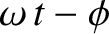
Figure 10.3 shows the intensity of the interference pattern generated when the slit spacing is equal to the wavelength of the light.
It can be seen that the width of the central (i.e.,  ,
,  ) bright fringe has expanded to such
an extent that the fringe occupies almost half of the projection screen, leaving room for just two dark fringes on either
side of it.
) bright fringe has expanded to such
an extent that the fringe occupies almost half of the projection screen, leaving room for just two dark fringes on either
side of it.
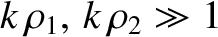
Finally, Figure 10.4 shows the intensity of the interference pattern generated when the slit spacing is much less than the
wavelength of the light. It can be seen that the width of the central bright fringe has expanded to
such an extent that the band occupies the whole projection screen, and there are no dark fringes. Indeed,
 becomes constant
in the limit that
becomes constant
in the limit that
 , in which case the interference pattern entirely disappears.
Figures 10.2–10.3 imply that the two-slit, far-field interference apparatus shown in Figure 10.1
only generates an interesting interference pattern when the slit spacing, , is greater than the
wavelength, , of the light.
Suppose that the plane wave that illuminates the interference apparatus is not normally incident on the slits, but instead propagates at an angle  to the -axis, as
shown in Figure 10.5. In this case, the incident wavefunction (10.1) becomes
to the -axis, as
shown in Figure 10.5. In this case, the incident wavefunction (10.1) becomes
, ) is
 , whereas the phase of the light incident on the second slit (located at
, ) is
, whereas the phase of the light incident on the second slit (located at
, ) is
 . Assuming that the cylindrical waves
emitted by each slit have the same phase (at the slits) as the plane wave that illuminates them, Equation (10.2)
generalizes to
where
. Assuming that the cylindrical waves
emitted by each slit have the same phase (at the slits) as the plane wave that illuminates them, Equation (10.2)
generalizes to
where
 and
and
 .
Hence, making use of the far-field orderings (10.10), and a standard trigonometric identity, we obtain
.
Hence, making use of the far-field orderings (10.10), and a standard trigonometric identity, we obtain
For the sake of simplicity, let us consider the limit
 , in which the innermost (i.e., low ) interference
fringes are located at small . (The projection screen is approximately planar in this limit, as
indicated in Figure 10.5, because a sufficiently small section of a cylindrical surface looks like a plane.) Assuming that is also small, the previous expression reduces to
, in which the innermost (i.e., low ) interference
fringes are located at small . (The projection screen is approximately planar in this limit, as
indicated in Figure 10.5, because a sufficiently small section of a cylindrical surface looks like a plane.) Assuming that is also small, the previous expression reduces to
![$\displaystyle {\cal I}(\theta) \propto\cos^2\left[\pi\,\frac{d}{\lambda}\,(\theta-\theta_0)\right].$](img3308.png) |
(10.19) |
 |
(10.20) |
is an integer. We conclude that if the slits
in a two-slit interference apparatus, such as that shown in Figure 10.5, are illuminated by an obliquely incident plane wave then the consequent phase difference between the
cylindrical waves emitted by each slit produces an angular shift in the interference pattern appearing on the projection screen.
To be more exact, the angular shift is equal to the angle of incidence, , of the plane wave, so that the central ()
bright fringe in the interference pattern is located at
 . See Figure 10.5. This is equivalent to saying that the
position of the central bright fringe can be determined via the rules of geometric optics. (This conclusion holds
even when is not small.)
. See Figure 10.5. This is equivalent to saying that the
position of the central bright fringe can be determined via the rules of geometric optics. (This conclusion holds
even when is not small.)

![\includegraphics[width=0.85\textwidth]{Chapter10/fig10_01.eps}](img3263.png)

![$\displaystyle \rho_1 = R\left(1-\frac{d}{R}\,\sin\theta + \frac{1}{4}\,\frac{d^...
...,\frac{d}{R}\,\sin\theta + {\cal O}\left(\frac{d^{\,2}}{R^{\,2}}\right)\right].$](img3270.png)


![\includegraphics[width=0.9\textwidth]{Chapter10/fig10_05.eps}](img3295.png)


![$\displaystyle \propto \cos\left[\omega\,t-k\,R-\frac{1}{2}\,(\phi_1+\phi_2)\right]\cos
\left[\frac{1}{2}\,k\,d\,\sin\theta-\frac{1}{2}\,(\phi_1-\phi_2)\right]$](img3304.png)
![$\displaystyle \propto \cos(\omega\,t-k\,R-\phi)\,\cos
\left[\frac{1}{2}\,k\,d\,(\sin\theta-\sin\theta_0)\right].$](img3305.png)
![$\displaystyle \psi(\theta,t)\propto \cos(\omega-k\,R-\phi)\,\cos
\left[\frac{1}{2}\,k\,d\,(\theta-\theta_0)\right],$](img3307.png)