Electromagnetic Waves
Consider a plane electromagnetic wave propagating through a vacuum in the  -direction.
Incidentally, electromagnetic waves are the only
commonly-occurring waves that do not require a medium through which to
propagate.
Suppose that the wave is linearly polarized in the
-direction.
Incidentally, electromagnetic waves are the only
commonly-occurring waves that do not require a medium through which to
propagate.
Suppose that the wave is linearly polarized in the  -direction; that is, its electric
component oscillates in the -direction. It follows that the magnetic
component of the wave oscillates in the
-direction; that is, its electric
component oscillates in the -direction. It follows that the magnetic
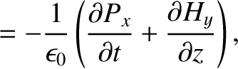
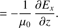
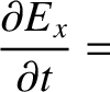
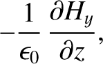
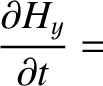
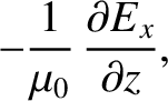
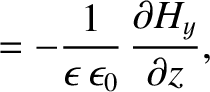
component of the wave oscillates in the  -direction (Fitzpatrick 2008). According to standard electromagnetic theory (see Appendix C), the wave is
described by the following pair of coupled partial differential equations:
where
-direction (Fitzpatrick 2008). According to standard electromagnetic theory (see Appendix C), the wave is
described by the following pair of coupled partial differential equations:
where  is the electric field-strength, and
  is the
magnetic intensity (i.e., the magnetic field-strength divided by
is the
magnetic intensity (i.e., the magnetic field-strength divided by
 ). Observe that Equations (6.116) and (6.117), which govern
the propagation of electromagnetic waves through a vacuum, are analogous
to Equations (6.53) and (6.54), which govern the propagation of
electromagnetic signals down a transmission line. In particular,
). Observe that Equations (6.116) and (6.117), which govern
the propagation of electromagnetic waves through a vacuum, are analogous
to Equations (6.53) and (6.54), which govern the propagation of
electromagnetic signals down a transmission line. In particular,  has units of
voltage over length,
has units of
voltage over length,  has units of current over length,
 has
units of capacitance per unit length, and has units of
inductance per unit length.
has
units of capacitance per unit length, and has units of
inductance per unit length.
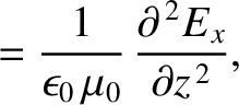
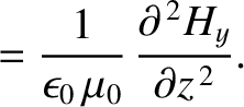
Equations (6.116) and (6.117) can be combined to give
It follows that the electric and the magnetic components of an electromagnetic wave
propagating through a vacuum both separately satisfy
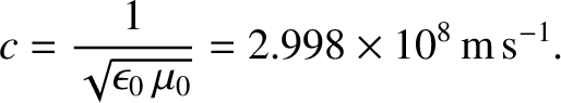
a wave equation of the form (6.1). Furthermore, the phase velocity of the
wave is the velocity of light in vacuum,
 |
(6.120) |
Let us search for a traveling wave solution of Equations (6.116) and (6.117), propagating in the
positive -direction, whose electric component has the form
 |
(6.121) |
This is a valid solution provided that
 |
(6.122) |
According to
Equation (6.117), the magnetic component of the wave is written
 |
(6.123) |
where
 |
(6.124) |
and  is the impedance of free space. [See Equation (6.74).]
Thus, the electric and magnetic components of an electromagnetic wave propagating through a vacuum are mutually perpendicular,
and also perpendicular to the direction of propagation. Moreover, the two components
oscillate in phase (i.e., they have simultaneous maxima and zeros), and
the amplitude of the magnetic component is that of the electric component
divided by the impedance of free space.
is the impedance of free space. [See Equation (6.74).]
Thus, the electric and magnetic components of an electromagnetic wave propagating through a vacuum are mutually perpendicular,
and also perpendicular to the direction of propagation. Moreover, the two components
oscillate in phase (i.e., they have simultaneous maxima and zeros), and
the amplitude of the magnetic component is that of the electric component
divided by the impedance of free space.
Multiplying Equation (6.116) by
 , Equation (6.117)
by
, Equation (6.117)
by
 , and adding the two resulting expressions, we obtain the
energy conservation equation
, and adding the two resulting expressions, we obtain the
energy conservation equation
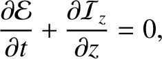 |
(6.125) |
where
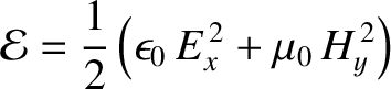 |
(6.126) |
is the energy density (i.e., energy per unit volume) of the wave (Fitzpatrick 2008), whereas
 |
(6.127) |
is the energy flux (i.e., power per unit area) in the positive -direction. (See Appendix C.) The mean energy flux associated with the -directed electromagnetic wave specified
in Equations (6.121) and (6.123) is thus
 |
(6.128) |
For a similar wave propagating in the negative -direction, it can be
demonstrated that
and
 |
(6.131) |
Consider a plane electromagnetic wave, linearly polarized in the -direction, that
propagates in the -direction through a transparent dielectric medium, such as glass or water. As is well-known (Fitzpatrick 2008), the electric component of the wave causes the neutral molecules making
up the medium to polarize; that is, it causes a small separation to develop between the mean positions of the positively
and negatively charged constituents of the molecules (i.e., the atomic nuclei and the
orbiting electrons). [Incidentally, it can be
shown that the magnetic component of the wave has a negligible influence on the
molecules, provided the wave amplitude is sufficiently small that the wave electric
field does not cause the electrons and nuclei to move with relativistic velocities (ibid.).] If the mean position of the positively charged
constituents of a given molecule, of net charge  , develops a vector displacement
 with respect to the mean position of the negatively charged constituents, of net charge
  , in response to a wave electric field
  , then the
associated electric dipole moment is
, then the
associated electric dipole moment is
 , where
is generally parallel to (ibid.). Furthermore, if there are
, where
is generally parallel to (ibid.). Furthermore, if there are  such molecules per unit volume then the electric dipole moment per unit volume
is written
such molecules per unit volume then the electric dipole moment per unit volume
is written
 . In a linear, isotropic, dielectric medium (ibid.),
 |
(6.132) |
where
 is a dimensionless quantity, known as the relative dielectric
constant, that is a property of the medium in question. In the presence of
a dielectric medium, Equations (6.116) and (6.117) generalize to give
(See Appendix C.)
When combined with Equation (6.132), these expressions yield
It can be seen that the previous equations are just like the corresponding vacuum equations,
(6.116) and (6.117), except that
has been replaced by
is a dimensionless quantity, known as the relative dielectric
constant, that is a property of the medium in question. In the presence of
a dielectric medium, Equations (6.116) and (6.117) generalize to give
(See Appendix C.)
When combined with Equation (6.132), these expressions yield
It can be seen that the previous equations are just like the corresponding vacuum equations,
(6.116) and (6.117), except that
has been replaced by
 . It immediately follows that the phase velocity of an
electromagnetic wave propagating through a dielectric medium is
. It immediately follows that the phase velocity of an
electromagnetic wave propagating through a dielectric medium is
 |
(6.137) |
where
 is the velocity of light in vacuum, and
the dimensionless quantity
is the velocity of light in vacuum, and
the dimensionless quantity
 |
(6.138) |
is known as the refractive index of the medium. Thus, an electromagnetic
wave propagating through a transparent dielectric medium does so at a
phase velocity that is less than the velocity of light in vacuum by a
factor  (where
  ). The dispersion relation of the wave is thus
 |
(6.139) |
Furthermore, the impedance of a transparent dielectric medium becomes
 |
(6.140) |
where is the impedance of free space.
Incidentally, the signal that travels down a transmission line is a form of guided electromagnetic wave. It follows
that if the space between the two conductors that constitute the line is filled with dielectric material of
relative dielectric constant  then the signal propagates down the line at the
reduced phase velocity
then the signal propagates down the line at the
reduced phase velocity
 |
(6.141) |
This occurs because the dielectric material
increases the capacitance per unit length of the line by a factor , but leaves the
inductance per unit length unchanged. (See Section 6.6.) For the same reason, the presence of the dielectric
material decreases the impedance of the line by a factor
 . Hence, the impedance of a
dielectric filled co-axial cable is [cf., Equation (6.78)]
. Hence, the impedance of a
dielectric filled co-axial cable is [cf., Equation (6.78)]
 |
(6.142) |
Here,  and
and  are the radii of the inner and outer conductors, respectively.
Suppose that the plane  forms the interface between two transparent dielectric
media of refractive indices
forms the interface between two transparent dielectric
media of refractive indices  and
and  . Let the first medium occupy the
region
. Let the first medium occupy the
region  , and the second the region
  . Suppose that a plane electromagnetic
wave, linearly polarized in the -direction, and propagating in the positive -direction, is launched toward the interface
from a wave source of angular frequency
. Suppose that a plane electromagnetic
wave, linearly polarized in the -direction, and propagating in the positive -direction, is launched toward the interface
from a wave source of angular frequency  situated at
  . We expect the
wave incident on the interface to be partly reflected, and partly transmitted.
The wave electric and magnetic fields in the region are written
. We expect the
wave incident on the interface to be partly reflected, and partly transmitted.
The wave electric and magnetic fields in the region are written
where  is the amplitude of (the electric component of) the incident wave,
  the amplitude of the reflected wave,
 , and
, and
 .
The wave electric and magnetic fields in the region take the form
where
.
The wave electric and magnetic fields in the region take the form
where  is the amplitude of the transmitted wave,
 , and
, and
 .
According to standard electromagnetic theory (see Appendix C), the appropriate matching conditions at the
interface () are that and are both continuous. Thus,
continuity of yields
.
According to standard electromagnetic theory (see Appendix C), the appropriate matching conditions at the
interface () are that and are both continuous. Thus,
continuity of yields
 |
(6.147) |
whereas continuity of gives
 |
(6.148) |
because
 .
It follows that
The coefficient of reflection,
.
It follows that
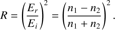
The coefficient of reflection,  , is defined as the ratio of the reflected to the incident energy
flux, so that
, is defined as the ratio of the reflected to the incident energy
flux, so that
 |
(6.151) |
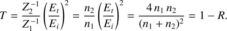
Likewise, the coefficient of transmission,  , is the ratio of the
transmitted to the incident energy flux, so that
, is the ratio of the
transmitted to the incident energy flux, so that
 |
(6.152) |
It can be seen, first of all, that if  then
then  and
and  .
In other words, if the two media have the same indices of refraction then
there is no reflection at the interface between them, and the transmitted
wave is consequently equal in amplitude to the incident wave. On the other
hand, if
.
In other words, if the two media have the same indices of refraction then
there is no reflection at the interface between them, and the transmitted
wave is consequently equal in amplitude to the incident wave. On the other
hand, if
 then there is always some reflection at the interface. Indeed,
the amplitude of the reflected wave is roughly proportional to the difference between and . This has important practical consequences.
We can only see a clean pane of glass in a window because some of the light incident
on an air/glass interface is reflected, as a consequence of the different refractive indices
of air and glass. As is well-known, it is a lot more difficult to see glass when it is submerged in water. This is because the refractive indices of glass and water are quite similar, and so there is very little reflection of light
incident on a water/glass interface.
then there is always some reflection at the interface. Indeed,
the amplitude of the reflected wave is roughly proportional to the difference between and . This has important practical consequences.
We can only see a clean pane of glass in a window because some of the light incident
on an air/glass interface is reflected, as a consequence of the different refractive indices
of air and glass. As is well-known, it is a lot more difficult to see glass when it is submerged in water. This is because the refractive indices of glass and water are quite similar, and so there is very little reflection of light
incident on a water/glass interface.
According to Equation (6.149),  when
when  .
The negative sign indicates a
.
The negative sign indicates a  radian phase shift of the (electric component of the) reflected wave, with
respect to the incident wave. We conclude that there is a radian phase shift of the reflected wave, relative to the incident wave, on reflection from an
interface with a
medium of greater refractive index. Conversely, there is zero
phase shift
on reflection from an interface with a medium of lesser refractive index. (This effect is important in thin-film interference. See Section 10.5.)
radian phase shift of the (electric component of the) reflected wave, with
respect to the incident wave. We conclude that there is a radian phase shift of the reflected wave, relative to the incident wave, on reflection from an
interface with a
medium of greater refractive index. Conversely, there is zero
phase shift
on reflection from an interface with a medium of lesser refractive index. (This effect is important in thin-film interference. See Section 10.5.)
Equations (6.149)–(6.152) are analogous to Equations (6.87)–(6.90), with the inverse of the refractive index playing the role of
impedance. This suggests, by analogy with earlier analysis, that we
can prevent reflection of an electromagnetic wave normally incident at an interface between two
transparent dielectric media of different refractive indices by separating the media in question
by a thin transparent layer whose thickness is one quarter of a wavelength, and whose
refractive index is the geometric mean of the refractive indices of the two
media. This is the physical principle behind the non-reflective lens coatings used
in high-quality optical instruments. (See Exercise 15.)