The first equation is simply Gauss' law (see Sect. 4). This equation describes how electric charges generate electric fields. Gauss' law states that:
The electric flux through any closed surface is equal to the total charge enclosed by the surface, divided byThis can be written mathematically as.
| (305) |
The second equation is the magnetic equivalent of Gauss' law (see Sect. 8.10). This equation describes how the non-existence of magnetic monopoles causes magnetic field-lines to form closed loops. Gauss' law for magnetic fields states that:
The magnetic flux through any closed surface is equal to zero.This can be written mathematically as
The third equation is Faraday's law (see Sect. 9.3). This equation describes how changing magnetic fields generate electric fields. Faraday's law states that:
The line integral of the electric field around any closed loop is equal to minus the time rate of change of the magnetic flux through the loop.This can be written mathematically as
The fourth, and final, equation is Ampère's circuital law (see Sect. 8.7). This equation describes how electric currents generates magnetic fields. Ampère's circuital law states that:
The line integral of the magnetic field around any closed loop is equal toThis can be written mathematically astimes the algebraic sum of the currents which pass through the loop.
| (309) |
When Maxwell first wrote Eqs. (306), (307), (308), and (310) he was basically trying to summarize everything which was known at the time about electric and magnetic fields in mathematical form. However, the more Maxwell looked at his equations, the more convinced he became that they were incomplete. Eventually, he proposed adding a new term, called the displacement current, to the right-hand side of his fourth equation. In fact, Maxwell was able to show that (306), (307), (308), and (310) are mathematically inconsistent unless the displacement current term is added to Eq. (310). Unfortunately, Maxwell's demonstration of this fact requires some advanced mathematical techniques which lie well beyond the scope of this course. In the following, we shall give a highly simplified version of his derivation of the missing term.
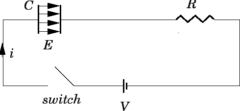
Consider a circuit
consisting of a parallel plate capacitor of capacitance ![]() in series with a
resistance
in series with a
resistance ![]() and an steady emf
and an steady emf ![]() , as shown in Fig. 52. Let
, as shown in Fig. 52. Let ![]() be the area of
the capacitor plates, and let
be the area of
the capacitor plates, and let ![]() be their separation. Suppose that
the switch is closed at
be their separation. Suppose that
the switch is closed at ![]() . The current
. The current ![]() flowing around the circuit
starts from an initial value of
flowing around the circuit
starts from an initial value of ![]() , and gradually decays to zero
on the RC time of the circuit (see Sect. 10.5).
Simultaneously, the charge
, and gradually decays to zero
on the RC time of the circuit (see Sect. 10.5).
Simultaneously, the charge ![]() on the
positive plates of the capacitor starts from zero, and gradually increases
to a final value of
on the
positive plates of the capacitor starts from zero, and gradually increases
to a final value of ![]() . As the charge
. As the charge ![]() varies, so does the
potential
difference
varies, so does the
potential
difference ![]() between the capacitor plates, since
between the capacitor plates, since ![]() .
.
The electric field in the region between the plates is approximately uniform,
directed perpendicular to the plates (running from the positively charged plate
to the negatively charged plate), and is of magnitude ![]() . It follows
that
. It follows
that
| (311) |
| (312) |
| (313) |
Equation (314) relates the instantaneous current flowing around the
circuit to the time rate of change of the electric field between the
capacitor plates. According to Eq. (310), the current flowing around the
circuit generates a magnetic field. This field circulates around the
current carrying wires
connecting the various components of the circuit. However, since
there is no actual current flowing between the
plates of the capacitor, no magnetic field is generated in this region,
according to Eq. (310).
Maxwell demonstrated that for reasons of mathematical self-consistency there
must, in fact, be a magnetic field generated in the
region between the plates of the capacitor.
Furthermore, this magnetic field must be the same as that which
would be generated if the
current ![]() (i.e., the same current as that which
flows around the rest of the circuit)
flowed between the plates. Of course, there is no actual current flowing between
the plates. However, there is a changing electric field. Maxwell argued that a
changing electric field constitutes an effective current (i.e., it
generates a magnetic field in just the same manner as an actual current).
For historical reasons (which do not particularly interest us at the moment), Maxwell
called this type of current a displacement current.
Since the displacement
current
(i.e., the same current as that which
flows around the rest of the circuit)
flowed between the plates. Of course, there is no actual current flowing between
the plates. However, there is a changing electric field. Maxwell argued that a
changing electric field constitutes an effective current (i.e., it
generates a magnetic field in just the same manner as an actual current).
For historical reasons (which do not particularly interest us at the moment), Maxwell
called this type of current a displacement current.
Since the displacement
current ![]() flowing between the plates of the capacitor must equal the
current
flowing between the plates of the capacitor must equal the
current ![]() flowing around the rest of the circuit, it follows from Eq. (314)
that
flowing around the rest of the circuit, it follows from Eq. (314)
that
Equation (315) was derived for the special case of the changing electric
field generated in the region
between the plates of a charging parallel plate capacitor. Nevertheless, this equation turns out to be completely general. Note that
![]() is equal to the electric flux
is equal to the electric flux ![]() between the plates of
the capacitor. Thus, the most general expression for the displacement current
passing through some closed loop is
between the plates of
the capacitor. Thus, the most general expression for the displacement current
passing through some closed loop is
| (316) |
According to Maxwell's argument, a displacement current is just as effective at generating a magnetic field as a real current. Thus, we need to modify Ampère's circuital law to take displacement currents into account. The modified law, which is known as the Ampère-Maxwell law, is written
The line integral of the electric field around any closed loop is equal toThis can be written mathematically as
| (317) |
Equations (306), (307), (308), and (318) are known collectively as Maxwell's equations. They constitute a complete and mathematically self-consistent description of the behaviour of electric and magnetic fields.