


Next: Transformers
Up: Inductance
Previous: The Circuit
The  Circuit
Let us now discuss a topic which, admittedly, has nothing whatsoever to
do with inductors, but is mathematically so similar to the topic just discussed
that it seems sensible to consider it at
this point.
Consider a circuit in which a battery of emf  is connected in series with
a capacitor of capacitance
is connected in series with
a capacitor of capacitance  , and a resistor of resistance
  .
For fairly obvious reasons, such a circuit is generally referred to as
an circuit. In steady-state, the charge on the positive plate
of the capacitor is given by
.
For fairly obvious reasons, such a circuit is generally referred to as
an circuit. In steady-state, the charge on the positive plate
of the capacitor is given by  , and zero current flows around the circuit
(since current cannot flow across the insulating gap between the capacitor
plates).
, and zero current flows around the circuit
(since current cannot flow across the insulating gap between the capacitor
plates).
Figure 49:
An circuit with a switch.
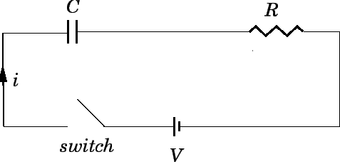 |
Let us now introduce a switch into the circuit, as shown in Fig. 49. Suppose
that the switch is initially open, but is suddenly closed at  . It is
assumed that the capacitor plates are uncharged when the switch is thrown.
We expect a transient current
. It is
assumed that the capacitor plates are uncharged when the switch is thrown.
We expect a transient current  to flow around the circuit until
the charge
to flow around the circuit until
the charge  on the positive plate of the capacitor attains its
final steady-state value . But, how long does this process take?
on the positive plate of the capacitor attains its
final steady-state value . But, how long does this process take?
The potential difference  between the positive and negative plates
of the capacitor is given by
between the positive and negative plates
of the capacitor is given by
 |
(268) |
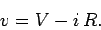
In other words, the potential difference between the plates is the emf
of the battery minus the potential drop across the resistor. The charge
on the positive plate of the capacitor is written
 |
(269) |
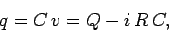
where is the final charge. Now, if is the instantaneous current
flowing around the circuit, then in a short time interval  the
charge on the positive plate of the capacitor increases by a
small amount
the
charge on the positive plate of the capacitor increases by a
small amount  (since all of the charge
which flows around the circuit must accumulate on the plates of the
capacitor). It follows that
(since all of the charge
which flows around the circuit must accumulate on the plates of the
capacitor). It follows that
 |
(270) |
Thus, the instantaneous current flowing around the circuit is
numerically equal to the rate at which the charge accumulated
on the positive plate of
the capacitor increases with time. Equations (269) and
(270) can be combined together to give
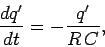 |
(271) |
where
 |
(272) |
At , just after the switch is closed, the charge on the positive
plate of the capacitor is zero, so
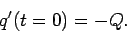 |
(273) |
Integration of Eq. (271), subject to the boundary condition
(273), yields
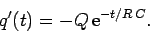 |
(274) |
It follows from Eq. (272) that
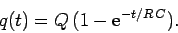 |
(275) |
The above expression specifies the charge on the positive plate of
the capacitor a time interval  after the switch is closed
(at time ). The variation of the charge with time is
sketched in Fig. 50.
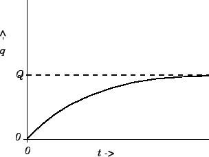
It can be seen that when the switch is closed the charge on the
positive plate of the capacitor
does not suddenly jump up to its final value, . Instead, the charge
increases smoothly from zero, and gradually asymptotes to its final value.
The charge has risen to approximately
after the switch is closed
(at time ). The variation of the charge with time is
sketched in Fig. 50.
It can be seen that when the switch is closed the charge on the
positive plate of the capacitor
does not suddenly jump up to its final value, . Instead, the charge
increases smoothly from zero, and gradually asymptotes to its final value.
The charge has risen to approximately  of its final value a
time
of its final value a
time
 |
(276) |
after the switch is closed. By the time  , the charge has risen to
more than
, the charge has risen to
more than  of its final value. Thus,
  is a good measure of
how long after the
switch is closed it takes for the capacitor to fully charge up.
The quantity
is a good measure of
how long after the
switch is closed it takes for the capacitor to fully charge up.
The quantity  is termed the time-constant, or the time, of the circuit.
Figure 50:
Sketch of the charging phase in an circuit switched on at .
 |
According to Eqs. (270) and (271),
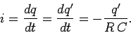 |
(277) |
It follows from Eq. (274) that
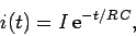 |
(278) |
where  . The above expression specifies the current flowing
around the circuit a time interval after the switch is closed
(at time ). It can be seen that, immediately after the switch is
thrown, the current which flows in the circuit is that which would
flow if the capacitor were replaced by a conducting wire. However, this
current is only transient, and rapidly decays away to a negligible value.
After one time, the current has decayed to 37% of its initial value.
After five times, the current has decayed to less than 1% of its initial
value. It is interesting to note that for a short instant of time,
just after the
switch is closed, the current in the circuit acts as if there is no insulating
gap between the capacitor plates. It essentially takes an time for the
information about the break in the
circuit to propagate around the circuit, and cause the current to stop
flowing.
. The above expression specifies the current flowing
around the circuit a time interval after the switch is closed
(at time ). It can be seen that, immediately after the switch is
thrown, the current which flows in the circuit is that which would
flow if the capacitor were replaced by a conducting wire. However, this
current is only transient, and rapidly decays away to a negligible value.
After one time, the current has decayed to 37% of its initial value.
After five times, the current has decayed to less than 1% of its initial
value. It is interesting to note that for a short instant of time,
just after the
switch is closed, the current in the circuit acts as if there is no insulating
gap between the capacitor plates. It essentially takes an time for the
information about the break in the
circuit to propagate around the circuit, and cause the current to stop
flowing.
Suppose that we take a capacitor of capacitance , which is charged to a voltage
, and discharge it by connecting a resistor of resistance across
its terminals at . How long does it take for the capacitor to
discharge? By analogy with the previous analysis, the charge on the
positive plate of the capacitor at time is given by
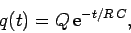 |
(279) |
where is the initial charge on the positive plate. It can be seen that
it takes a few times for the capacitor to fully discharge.
The current which flows through the resistor is
|
(280) |
where is the initial current. It can be seen that the capacitor
initially acts like a battery of emf (since it drives the current
across the resistor), but that, as it discharges, its effective
emf decays to a negligible value on a few times.
Next: Transformers
Up: Inductance
Previous: The Circuit
Richard Fitzpatrick
2007-07-14