Next: Pulse Propagation in Two Up: Dispersive Waves Previous: Electromagnetic Waves in Conductors Contents
 , where
  is the velocity of light and
  the signal frequency (in hertz).
Unfortunately, conventional transmission lines are subject to radiative losses (because the lines effectively act as antennas)
that increase as the fourth power of the signal frequency (Fitzpatrick 2008). Above a certain critical frequency, which typically
lies in the microwave band, the radiative losses become intolerably large. Under these circumstances, the transmission line must be
replaced by a device known as a waveguide. A waveguide is basically a long hollow metal box within
which electromagnetic signals propagate. Provided the walls of the box are much thicker than the skin-depth (see Section 9.9) in the wall material,
the signal is essentially isolated from the outside world, and radiative losses are consequently negligible.
the signal frequency (in hertz).
Unfortunately, conventional transmission lines are subject to radiative losses (because the lines effectively act as antennas)
that increase as the fourth power of the signal frequency (Fitzpatrick 2008). Above a certain critical frequency, which typically
lies in the microwave band, the radiative losses become intolerably large. Under these circumstances, the transmission line must be
replaced by a device known as a waveguide. A waveguide is basically a long hollow metal box within
which electromagnetic signals propagate. Provided the walls of the box are much thicker than the skin-depth (see Section 9.9) in the wall material,
the signal is essentially isolated from the outside world, and radiative losses are consequently negligible.
Consider an evacuated waveguide of rectangular cross-section that runs along the  -direction, and is enclosed by perfectly conducting
(i.e., infinite conductivity) metal walls located at
-direction, and is enclosed by perfectly conducting
(i.e., infinite conductivity) metal walls located at  ,
,  ,
,  , and
, and  . Suppose that an electromagnetic
wave propagates along the waveguide in the -direction. For the sake of simplicity, let there be no
. Suppose that an electromagnetic
wave propagates along the waveguide in the -direction. For the sake of simplicity, let there be no  -variation of the wave electric or magnetic fields.
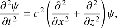
The wave propagation inside the waveguide is governed by the two-dimensional wave equation [cf., Equation (7.9)]
-variation of the wave electric or magnetic fields.
The wave propagation inside the waveguide is governed by the two-dimensional wave equation [cf., Equation (7.9)]
 represents the electric component of the wave, which is assumed to be everywhere parallel to the -axis,
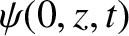
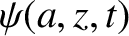
and is the velocity of light in vacuum. The appropriate boundary conditions are
because the electric field inside a perfect conductor is zero (otherwise, an infinite current would flow), and, according to standard electromagnetic
theory (see Appendix C), there cannot be a tangential discontinuity in the electric
field at a conductor/vacuum boundary. (There can, however, be a normal discontinuity. This permits
represents the electric component of the wave, which is assumed to be everywhere parallel to the -axis,
and is the velocity of light in vacuum. The appropriate boundary conditions are
because the electric field inside a perfect conductor is zero (otherwise, an infinite current would flow), and, according to standard electromagnetic
theory (see Appendix C), there cannot be a tangential discontinuity in the electric
field at a conductor/vacuum boundary. (There can, however, be a normal discontinuity. This permits  to be non-zero at and .)
Let us search for a separable solution of Equation (9.221) of the form
where represents the -component of the wavevector (rather than its magnitude), and is the
effective wavenumber for propagation along the waveguide.
The previous solution automatically satisfies the boundary condition (9.222). The second boundary
condition (9.223) is satisfied provided
represents the -component of the wavevector (rather than its magnitude), and is the
effective wavenumber for propagation along the waveguide.
The previous solution automatically satisfies the boundary condition (9.222). The second boundary
condition (9.223) is satisfied provided
 |
(9.225) |
 is a positive integer. Suppose that takes its smallest possible value
  .
( cannot be zero, because, in this case,
.
( cannot be zero, because, in this case,  everywhere.)
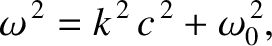
Substitution of expression (9.224) into the wave equation (9.221) yields the dispersion relation
where
everywhere.)
Substitution of expression (9.224) into the wave equation (9.221) yields the dispersion relation
where
 |
(9.227) |
 ,
playing the role of the (electron) plasma frequency,
,
playing the role of the (electron) plasma frequency,
 . The cutoff frequency is so-called because
for
. The cutoff frequency is so-called because
for
 the wavenumber is imaginary (i.e.,
  ), which implies that the
wave does not propagate along the waveguide, but, instead, decays exponentially with increasing .
On the other hand, for wave frequencies above the cutoff frequency the phase velocity,
), which implies that the
wave does not propagate along the waveguide, but, instead, decays exponentially with increasing .
On the other hand, for wave frequencies above the cutoff frequency the phase velocity,
 |
(9.228) |
 |
(9.229) |
 , because the signal ceases to
propagate at all when
, because the signal ceases to
propagate at all when
 .
.
It turns out that waveguides support many distinct modes of propagation. The type of mode
discussed previously is termed a TE (for transverse electric-field) mode, because the electric
field is transverse to the direction of propagation. (See Exercise 17.) There are many different sorts of TE mode, corresponding, for instance, to
different choices of the mode number, (Fitzpatrick 2008). However, the  mode has the lowest cutoff frequency.
There are also
TM (for transverse magnetic-field) modes (see Exercise 18), and TEM (for transverse electric- and magnetic-field) modes (ibid.).
TM modes also only propagate when the wave frequency exceeds a cutoff frequency. On the other hand, TEM modes (which are the same type of mode as that supported by
a conventional transmission line) propagate at all frequencies. However, TEM modes are only possible when the waveguide possesses an internal
conductor running along its length (ibid.).
mode has the lowest cutoff frequency.
There are also
TM (for transverse magnetic-field) modes (see Exercise 18), and TEM (for transverse electric- and magnetic-field) modes (ibid.).
TM modes also only propagate when the wave frequency exceeds a cutoff frequency. On the other hand, TEM modes (which are the same type of mode as that supported by
a conventional transmission line) propagate at all frequencies. However, TEM modes are only possible when the waveguide possesses an internal
conductor running along its length (ibid.).