Next: Waveguides Up: Dispersive Waves Previous: Perpendicular EM Waves in Contents
 |
(9.200) |
 is the current density (i.e., the current per unit area),
  the
electric field-strength, and
the
electric field-strength, and  a constant known as the electrical conductivity
of the medium in question.
The
a constant known as the electrical conductivity
of the medium in question.
The  -directed propagation of a plane electromagnetic
wave, linearly polarized in the
-directed propagation of a plane electromagnetic
wave, linearly polarized in the  -direction, through an Ohmic conductor of conductivity is
governed by (see Appendix C)
-direction, through an Ohmic conductor of conductivity is
governed by (see Appendix C)
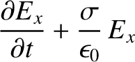 |
 |
(9.201) |
 |
 |
(9.202) |
 , the first term on the
left-hand side of Equation (9.201) is negligible with respect to the
second term, and the previous two equations reduce to
These equations can be solved to give
where
and
(See Exercise 7.)
Equations (9.205) and (9.206) indicate that the amplitude of an electromagnetic
wave propagating through a conductor decays exponentially on a characteristic lengthscale,
, the first term on the
left-hand side of Equation (9.201) is negligible with respect to the
second term, and the previous two equations reduce to
These equations can be solved to give
where
and
(See Exercise 7.)
Equations (9.205) and (9.206) indicate that the amplitude of an electromagnetic
wave propagating through a conductor decays exponentially on a characteristic lengthscale,
 , that is known as the skin-depth. Consequently, an electromagnetic wave
cannot penetrate more than a few skin-depths into a conducting medium. The skin-depth
is smaller at higher frequencies. This implies that high-frequency waves penetrate
a shorter distance into a conductor than low-frequency waves.
, that is known as the skin-depth. Consequently, an electromagnetic wave
cannot penetrate more than a few skin-depths into a conducting medium. The skin-depth
is smaller at higher frequencies. This implies that high-frequency waves penetrate
a shorter distance into a conductor than low-frequency waves.
Consider a typical metallic conductor such as copper, whose electrical
conductivity at room temperature is about
 (Wikipedia contributors 2018). Copper, therefore, acts as a good
conductor for all electromagnetic waves of frequency below about
(Wikipedia contributors 2018). Copper, therefore, acts as a good
conductor for all electromagnetic waves of frequency below about
 . The skin-depth in copper for such waves is thus
 |
(9.209) |
 at 1 Hz, but only about
2 mm at 1 kHz. This gives rise to the so-called skin effect in copper wires, by which an oscillating electromagnetic
signal of increasing frequency, transmitted along such a wire, is confined
to an increasingly narrow layer (whose thickness is of order of the skin-depth)
on the surface of the wire.
at 1 Hz, but only about
2 mm at 1 kHz. This gives rise to the so-called skin effect in copper wires, by which an oscillating electromagnetic
signal of increasing frequency, transmitted along such a wire, is confined
to an increasingly narrow layer (whose thickness is of order of the skin-depth)
on the surface of the wire.
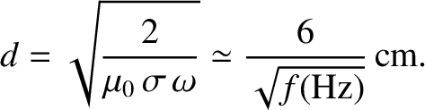
The conductivity of sea-water is only about
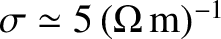 (Wikipedia contributors 2018). However, this is still sufficiently high for sea-water to act as
a good conductor for all radio frequency electromagnetic waves (i.e.,
(Wikipedia contributors 2018). However, this is still sufficiently high for sea-water to act as
a good conductor for all radio frequency electromagnetic waves (i.e.,
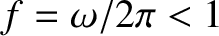 GHz). The skin-depth at 1 MHz (
 m)
is about
m)
is about  m, whereas that at 1 kHz (
km)
is still only about 7 m. This obviously poses quite severe restrictions for
radio communication with submerged submarines. Either the submarines
have to come quite close to the surface to communicate (which is dangerous), or the communication must be performed with extremely low-frequency (ELF) waves (i.e.,
m, whereas that at 1 kHz (
km)
is still only about 7 m. This obviously poses quite severe restrictions for
radio communication with submerged submarines. Either the submarines
have to come quite close to the surface to communicate (which is dangerous), or the communication must be performed with extremely low-frequency (ELF) waves (i.e.,  Hz). Unfortunately, such waves have very large wavelengths (
 ), which means
that they can only be efficiently generated by gigantic
antennas.
), which means
that they can only be efficiently generated by gigantic
antennas.
According to Equation (9.206), the phase of the magnetic component of an
electromagnetic wave propagating through a good conductor lags behind that of the
electric component by  radians. It follows that the mean energy flux into
the conductor takes the form (see Appendix C)
radians. It follows that the mean energy flux into
the conductor takes the form (see Appendix C)
 |
(9.210) |
 is the amplitude of the electric component of the
wave. The fact that the mean energy flux is positive indicates that some of the
wave energy is absorbed by the conductor. In fact, the absorbed energy corresponds
to the energy lost due to Joule heating within the conductor. (See Exercise 15.)
is the amplitude of the electric component of the
wave. The fact that the mean energy flux is positive indicates that some of the
wave energy is absorbed by the conductor. In fact, the absorbed energy corresponds
to the energy lost due to Joule heating within the conductor. (See Exercise 15.)
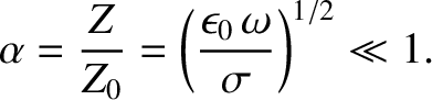
According to Equation (9.208), the impedance of a good conductor is far less than
that of a vacuum (i.e.,  ). This implies that the ratio of the magnetic
to the electric components of an electromagnetic wave propagating through a good conductor is far larger than that of a wave propagating through a vacuum. (This is because the conductor effectively “shorts out" the electric component of the wave.)
). This implies that the ratio of the magnetic
to the electric components of an electromagnetic wave propagating through a good conductor is far larger than that of a wave propagating through a vacuum. (This is because the conductor effectively “shorts out" the electric component of the wave.)
Suppose that the region  is a vacuum, and the region
  is
occupied by a good conductor of conductivity . Consider a linearly polarized plane wave,
normally incident on the interface. Let the wave electric and
magnetic fields in the vacuum region take the form of the incident and reflected waves specified in Equations (9.42) and (9.43).
The wave electric and magnetic fields in the conductor are written
is
occupied by a good conductor of conductivity . Consider a linearly polarized plane wave,
normally incident on the interface. Let the wave electric and
magnetic fields in the vacuum region take the form of the incident and reflected waves specified in Equations (9.42) and (9.43).
The wave electric and magnetic fields in the conductor are written
 |
 |
(9.211) |
 |
 |
(9.212) |
 is the amplitude of the evanescent wave that penetrates into the
conductor,
is the amplitude of the evanescent wave that penetrates into the
conductor,  is the phase of this wave with respect to the incident wave,
and
is the phase of this wave with respect to the incident wave,
and
 |
(9.213) |
 and
and  at the vacuum/conductor interface (
 ). (See Appendix C.)
In other words,
Equations (9.214) and (9.215), which must be satisfied at all times,
can be solved, in the limit
). (See Appendix C.)
In other words,
Equations (9.214) and (9.215), which must be satisfied at all times,
can be solved, in the limit
 , to give
(See Exercise 8.)
Hence, the coefficient of reflection becomes
, to give
(See Exercise 8.)
Hence, the coefficient of reflection becomes
According to the previous analysis, a good conductor reflects a normally incident
electromagnetic wave with a phase shift of almost  radians (i.e.,
 ). The coefficient of reflection is just less than unity, indicating that, while most
of the incident energy is reflected by the conductor, a small fraction of it
is absorbed.
). The coefficient of reflection is just less than unity, indicating that, while most
of the incident energy is reflected by the conductor, a small fraction of it
is absorbed.
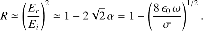
High-quality metallic mirrors are generally coated in silver, whose conductivity
is
 (Wikipedia contributors 2018). It follows, from Equation (9.220), that at optical
frequencies (
(Wikipedia contributors 2018). It follows, from Equation (9.220), that at optical
frequencies (
 ) the coefficient
of reflection of a silvered mirror is
) the coefficient
of reflection of a silvered mirror is
 . This implies that
about
. This implies that
about  of the light incident on the mirror is absorbed, rather than being reflected. This rather severe light loss can be
problematic in instruments, such as astronomical telescopes, that are used to
view faint objects.
of the light incident on the mirror is absorbed, rather than being reflected. This rather severe light loss can be
problematic in instruments, such as astronomical telescopes, that are used to
view faint objects.


![$\displaystyle \alpha\left[E_i\,\cos(\omega\,t) - E_r\,\cos(\omega\,t+\phi_r)\right]$](img2917.png)