Next: Reflection by Conducting Surfaces
Up: Wave Propagation in Inhomogeneous
Previous: Fresnel Relations
According to Equation (956), when light is obliquely incident at an interface between two dielectric media, the
angle of refraction  is related to the angle of incidence
  according to
 |
(1008) |
This formula presents no problems when  . However, if
 then the formula predicts that
 is greater than
unity when the angle of incidence exceeds some critical angle given by
is greater than
unity when the angle of incidence exceeds some critical angle given by
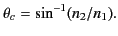 |
(1009) |
In this situation, the analysis of the previous section requires modification.
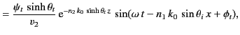
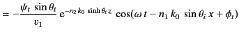
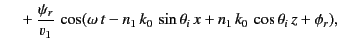
Consider the polarization in which the magnetic field is parallel to the interface.
We can write
in the region  , and
, and
in the region  . Here,
 |
(1016) |
The matching conditions (967) and (969) both yield
whereas the matching condition (970) gives
Here,
 |
(1021) |
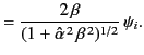
It follows that
Moreover,
 |
(1026) |
and
 |
(1027) |
The last result follows because  and
and  for the transmitted wave oscillate
  radians out of phase.
Hence, when the angle of incidence exceeds the critical angle, the coefficient of reflection is unity, and the coefficient of transmission zero.
radians out of phase.
Hence, when the angle of incidence exceeds the critical angle, the coefficient of reflection is unity, and the coefficient of transmission zero.
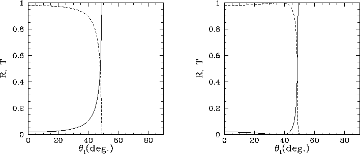
Figure:
Coefficients of reflection (solid curves) and transmission (dashed curves) for oblique incidence from water ( ) to
air (
) to
air ( ). The left-hand panel shows the wave polarization
for which the electric field is parallel to the interface, whereas the
right-hand panel shows the wave polarization for which the
magnetic field is parallel to the interface. The critical angle is
). The left-hand panel shows the wave polarization
for which the electric field is parallel to the interface, whereas the
right-hand panel shows the wave polarization for which the
magnetic field is parallel to the interface. The critical angle is
 .
.
 |
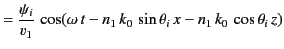
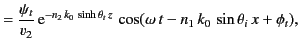
Consider the polarization in which the electric field is parallel to the interface.
We can write
in the region
, and
in the region
.
The matching conditions (993) and (997) both yield
whereas the matching condition (994) gives
It follows that
As before, if the angle of incidence exceeds the critical angle, the coefficient of reflection is unity, and the coefficient of transmission zero.
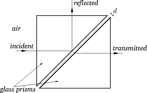
Figure 17:
Frustrated total internal reflection.
 |
According to the above analysis, when light is incident on an interface separating a medium of high
refractive index from a medium of low refractive index, and the angle of
incidence exceeds the critical angle,  , the transmitted ray becomes evanescent (i.e., its amplitude decays exponentially), and
all of the incident energy is reflected. This process is known as total internal reflection.
Figure 16 shows the coefficients of reflection and transmission
for oblique incidence from water (
) to
air (
). In this case, the critical angle is
, the transmitted ray becomes evanescent (i.e., its amplitude decays exponentially), and
all of the incident energy is reflected. This process is known as total internal reflection.
Figure 16 shows the coefficients of reflection and transmission
for oblique incidence from water (
) to
air (
). In this case, the critical angle is
 .
.
When total internal reflection takes place, the evanescent transmitted
wave penetrates a few wavelengths into the lower refractive index medium.
The existence of the evanescent wave can be demonstrated using the
apparatus pictured in Figure 17. This shows two right-angled
glass prisms separated by a small air gap of width  . Light incident
on the internal surface of the first prism is internally reflected (assuming that
. Light incident
on the internal surface of the first prism is internally reflected (assuming that
 ). However,
if the spacing
is not too much larger than the wavelength of the light (in air) then the
evanescent wave in the air gap still has a finite amplitude when it reaches the second prism. In this case, a detectable transmitted
wave is excited in the second prism. The amplitude of this
wave has an inverse exponential dependance on the width of the gap.
This effect is called frustrated total internal reflection, and
is analogous to the tunneling of wavefunctions through
potential barriers in quantum mechanics.
). However,
if the spacing
is not too much larger than the wavelength of the light (in air) then the
evanescent wave in the air gap still has a finite amplitude when it reaches the second prism. In this case, a detectable transmitted
wave is excited in the second prism. The amplitude of this
wave has an inverse exponential dependance on the width of the gap.
This effect is called frustrated total internal reflection, and
is analogous to the tunneling of wavefunctions through
potential barriers in quantum mechanics.
According to Equations (1024) and (1040), total internal reflection produces a phase shift,  , between the reflected
and the incident waves. Moreover, this phase shift is different for the two possible wave polarizations. Hence, if unpolarized
light is subject to total internal reflection then a phase advance,
, between the reflected
and the incident waves. Moreover, this phase shift is different for the two possible wave polarizations. Hence, if unpolarized
light is subject to total internal reflection then a phase advance,
 , is introduced between the different polarizations. (The phase of
the polarization in which the magnetic field is parallel to the interface is advanced with respect to that of the other polarization.)
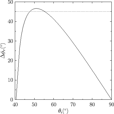
Figure 18 shows the phase advance due to total internal reflection at a glass/air interface, as a function of the angle of
incidence. Here, the refractive indices of the glass and air are taken to be
, is introduced between the different polarizations. (The phase of
the polarization in which the magnetic field is parallel to the interface is advanced with respect to that of the other polarization.)
Figure 18 shows the phase advance due to total internal reflection at a glass/air interface, as a function of the angle of
incidence. Here, the refractive indices of the glass and air are taken to be  and
, respectively.
It can be seen that there are two special values of the angle of incidence (i.e.,
and
, respectively.
It can be seen that there are two special values of the angle of incidence (i.e.,
 and
and
 ) at which the phase advance is
  radians.
Figure:
Phase advance introduced between the two different wave polarizations by total internal reflection at
an interface between glass (
) and air (
).
 |
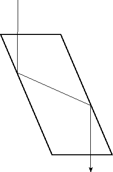
The aforementioned phase advance on total internal reflection is exploited in the so-called Fresnel rhomb to convert linearly
polarized light into circular polarized light. A Fresnel rhomb is a prism-like device (usually in the form
of a right-parallelepiped) that is shaped such that light entering one of the small faces is internally reflected twice (once from each of the two sloped faces) before exiting through the other small face. (See Figure 19.) The angle of internal reflection is the same in each case, and is designed to produces a
phase difference between the two wave polarizations. For the case of a prism made up of glass of refractive index  ,
this is achieved by ensuring that the reflection angle is either
or
. The net result of sending light though the device is thus to introduce a
phase difference between the
two polarizations. If the incoming light is linearly polarized at
,
this is achieved by ensuring that the reflection angle is either
or
. The net result of sending light though the device is thus to introduce a
phase difference between the
two polarizations. If the incoming light is linearly polarized at  to the plane of the incident and reflected waves then the
amplitudes of the two wave polarizations are the same. This ensures that the
phase difference introduced by the rhomb
produces circularly (rather than elliptically) polarized light. (See Section 7.6.)
to the plane of the incident and reflected waves then the
amplitudes of the two wave polarizations are the same. This ensures that the
phase difference introduced by the rhomb
produces circularly (rather than elliptically) polarized light. (See Section 7.6.)
Figure 19:
Path of light ray through Fresnel romb (schematic).
 |
Next: Reflection by Conducting Surfaces
Up: Wave Propagation in Inhomogeneous
Previous: Fresnel Relations
Richard Fitzpatrick
2014-06-27