


Next: Magnetic energy
Up: Magnetic induction
Previous: Self-inductance
Consider, now, two long thin solenoids, one wound on top of the other. The length
of each solenoid is  , and the common radius is
  . Suppose that the bottom
coil has
. Suppose that the bottom
coil has  turns per unit length, and carries a current
  . The magnetic
flux passing through each turn of the top coil is
. The magnetic
flux passing through each turn of the top coil is
 , and
the total flux linking the top coil is therefore
, and
the total flux linking the top coil is therefore
 , where
  is the number of turns per unit length in the top
coil. It follows that the mutual inductance of the two coils, defined
is the number of turns per unit length in the top
coil. It follows that the mutual inductance of the two coils, defined
 , is given by
 |
(916) |
Recall that the self-inductance of the bottom coil is
 |
(917) |
and that of the top coil is
 |
(918) |
Hence, the mutual inductance can be written
 |
(919) |
Note that this result depends on the assumption that all of the flux produced
by one coil passes through the other coil. In reality, some of the flux
leaks out, so that the mutual inductance is somewhat less than that given in the
above formula. We can write
 |
(920) |
where the constant  is called the coefficient of coupling,
and lies in the range
is called the coefficient of coupling,
and lies in the range
 .
.
Suppose that the two coils have resistances  and
and  . If the bottom coil
has an instantaneous current flowing through it, and a total voltage drop
. If the bottom coil
has an instantaneous current flowing through it, and a total voltage drop
 , then the voltage drop due to its resistance is
  . The voltage drop
due to the back e.m.f. generated by the self-inductance of the coil is
. The voltage drop
due to the back e.m.f. generated by the self-inductance of the coil is
 . There is also a back e.m.f. due to inductive coupling with
the top coil. We know that the flux through the bottom coil due to the instantaneous
current
. There is also a back e.m.f. due to inductive coupling with
the top coil. We know that the flux through the bottom coil due to the instantaneous
current  flowing in the top coil is
 |
(921) |
Thus, by Faraday's law and Lenz's law, the e.m.f. induced in the bottom
coil is
 |
(922) |
The voltage drop across the bottom coil due to its mutual inductance with the
top coil is minus this expression. Thus, the circuit equation for the bottom coil is
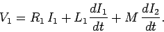 |
(923) |
Likewise, the circuit equation for the top coil is
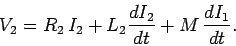 |
(924) |
Here,  is the total voltage drop across the top coil.
Suppose that we suddenly connect a battery of e.m.f.
to the bottom coil, at time  . The top coil is assumed to be
open-circuited, or connected to a voltmeter of very high internal resistance,
so that
. The top coil is assumed to be
open-circuited, or connected to a voltmeter of very high internal resistance,
so that  . What is the e.m.f. generated in the top coil?
Since , the circuit equation for the bottom coil is
. What is the e.m.f. generated in the top coil?
Since , the circuit equation for the bottom coil is
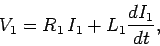 |
(925) |
where is constant, and  . We have already seen the solution to
this equation:
. We have already seen the solution to
this equation:
![\begin{displaymath}
I_1 = \frac{V_1}{R_1} \left[ 1 - \exp(-R_1 t/L_1) \right].
\end{displaymath}](img1931.png) |
(926) |
The circuit equation for the top coil is
 |
(927) |
giving
 |
(928) |
It follows from Eq. (920) that
 |
(929) |
Since
 , we obtain
 |
(930) |
Note that  is discontinuous at . This is not a problem, since the
resistance of the top circuit is infinite, so there is no discontinuity in the
current (and, hence, in the magnetic field). But, what about the displacement current,
which is proportional to
is discontinuous at . This is not a problem, since the
resistance of the top circuit is infinite, so there is no discontinuity in the
current (and, hence, in the magnetic field). But, what about the displacement current,
which is proportional to
 ? Surely, this is discontinuous
at (which is clearly unphysical)? The crucial point, here,
is that we have specifically
neglected the displacement current in all of our previous analysis, so it does not
make much sense to start worrying about it now. If we had retained the displacement
current in our calculations, then
we would have found that the voltage in the top circuit jumps up,
at , on a time-scale similar to the light traverse time across the circuit
(i.e., the jump is instantaneous to all intents and purposes, but the
displacement current remains finite).
? Surely, this is discontinuous
at (which is clearly unphysical)? The crucial point, here,
is that we have specifically
neglected the displacement current in all of our previous analysis, so it does not
make much sense to start worrying about it now. If we had retained the displacement
current in our calculations, then
we would have found that the voltage in the top circuit jumps up,
at , on a time-scale similar to the light traverse time across the circuit
(i.e., the jump is instantaneous to all intents and purposes, but the
displacement current remains finite).
Now,
 |
(931) |
so if  then the voltage in the bottom circuit is considerably amplified
in the top circuit. This effect is the basis for old-fashioned car ignition
systems. A large voltage spike is induced in a secondary circuit (connected to
a coil with very many turns) whenever the current in a primary circuit
(connected to a coil with not so many turns) is either switched on or off.
The primary circuit is connected to the car battery (whose e.m.f. is
typically 12 volts).
The switching is done by a set of points, which are mechanically opened and
closed as the engine turns. The large voltage spike induced in the secondary circuit,
as the points are either opened or closed, causes a spark to jump across a gap
in this circuit. This spark ignites a petrol/air mixture in one of the cylinders.
We might think that the optimum configuration is to have only one turn in the primary
circuit, and lots of turns in the secondary circuit, so that the ratio
then the voltage in the bottom circuit is considerably amplified
in the top circuit. This effect is the basis for old-fashioned car ignition
systems. A large voltage spike is induced in a secondary circuit (connected to
a coil with very many turns) whenever the current in a primary circuit
(connected to a coil with not so many turns) is either switched on or off.
The primary circuit is connected to the car battery (whose e.m.f. is
typically 12 volts).
The switching is done by a set of points, which are mechanically opened and
closed as the engine turns. The large voltage spike induced in the secondary circuit,
as the points are either opened or closed, causes a spark to jump across a gap
in this circuit. This spark ignites a petrol/air mixture in one of the cylinders.
We might think that the optimum configuration is to have only one turn in the primary
circuit, and lots of turns in the secondary circuit, so that the ratio
 is made as large as possible. However, this is not the case. Most of
the magnetic field lines generated by a single turn primary coil are likely to
miss the secondary coil altogether. This means that the coefficient of coupling
is small, which reduces the voltage induced in the secondary circuit. Thus, we
need a reasonable number of turns in the primary coil in order to localize the
induced magnetic field, so that it links effectively with the secondary coil.
is made as large as possible. However, this is not the case. Most of
the magnetic field lines generated by a single turn primary coil are likely to
miss the secondary coil altogether. This means that the coefficient of coupling
is small, which reduces the voltage induced in the secondary circuit. Thus, we
need a reasonable number of turns in the primary coil in order to localize the
induced magnetic field, so that it links effectively with the secondary coil.
Next: Magnetic energy
Up: Magnetic induction
Previous: Self-inductance
Richard Fitzpatrick
2006-02-02