Next: Complex Line Integrals
Up: Two-Dimensional Potential Flow
Previous: Schwarz-Christoffel Theorem
Consider a situation in which steady, incompressible, irrotational flow is partly bounded by rigid walls, and partly by free streamlines
of unknown shape on which the pressure takes a known constant value. For instance, the free streamlines
might correspond to the interface of a liquid with the atmosphere, in which case the constant pressure would correspond to that
of the atmosphere. According to Bernoulli's theorem, (6.40), (neglecting
gravity) the fluid speed is constant on a free streamline.
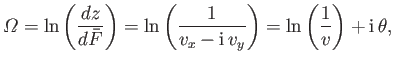
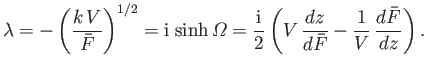
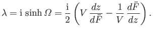
Let us define the new complex variable
 |
(6.89) |
where
 ,
,
 , and
, and  and
and  are the magnitude and direction (relative to the
  -axis) of the
velocity vector
-axis) of the
velocity vector
 . (See Section 6.5.) Here,
 ,
,
 , and
, and
 .
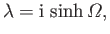
It follows that the real part of
.
It follows that the real part of
 is constant
on each free streamline, whereas the imaginary part is constant on each straight segment of the rigid boundary. Thus,
the whole boundary of the fluid is represented in the
-plane by a polygon.
We know, from the Schwarz-Christoffel theorem (see Section 6.8), that it is always possible to
map the interior (or exterior) of a polygon in one complex plane onto the upper half of another complex plane. Hence,
it is possible to find conformal relations between
and a new complex variable
is constant
on each free streamline, whereas the imaginary part is constant on each straight segment of the rigid boundary. Thus,
the whole boundary of the fluid is represented in the
-plane by a polygon.
We know, from the Schwarz-Christoffel theorem (see Section 6.8), that it is always possible to
map the interior (or exterior) of a polygon in one complex plane onto the upper half of another complex plane. Hence,
it is possible to find conformal relations between
and a new complex variable  , and
between
, and
between  and
, such that the flow region is mapped onto the upper half of the
-plane in both
cases. In this way, we can find a relation between
and
, from which an expression for
in terms of
and
, such that the flow region is mapped onto the upper half of the
-plane in both
cases. In this way, we can find a relation between
and
, from which an expression for
in terms of  follows via integration.
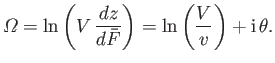
As an example of the application of free streamline theory, let us calculate the contraction ratio of a two-dimensional jet of liquid emerging from an orifice.
Suppose that the orifice in question is a long thin slot in a plane wall of small thickness, and that the wall forms part of a large vessel
containing liquid. The speed of the liquid on the free streamlines that emerge from the edges of the orifice is uniform, and equal to
 , say. This is also the speed of the interior of the jet far downstream of the orifice, where (neglecting the effects of gravity) the
streamlines are straight and parallel. (See Figure 6.16.) Let the two streamlines bounding the flow, on which
, say. This is also the speed of the interior of the jet far downstream of the orifice, where (neglecting the effects of gravity) the
streamlines are straight and parallel. (See Figure 6.16.) Let the two streamlines bounding the flow, on which
 and
and
 , say--be
 and
and  , respectively, where
  ,
,  ,
,  , and
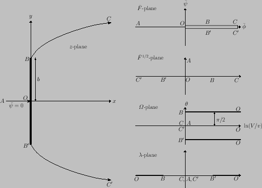
, and  all represent points at infinity. Figure 6.15 shows the corresponding
straight-line boundaries in the
- and
-planes, where
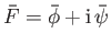
is now defined in a more convenient manner as
all represent points at infinity. Figure 6.15 shows the corresponding
straight-line boundaries in the
- and
-planes, where
is now defined in a more convenient manner as
 |
(6.90) |
Figure 6.15:
Conformal transformations required for the determination of the flow from an orifice in a plane wall in two
dimensions.
 |
We, first, need to map the semi-infinite strip  in the
-plane to the upper half of the
-plane.
The conformal transformation of a semi-infinite strip onto the upper half of another complex plane is achieved by the
relation (6.81). Adapting this relation to our current needs, we take
in the
-plane to the upper half of the
-plane.
The conformal transformation of a semi-infinite strip onto the upper half of another complex plane is achieved by the
relation (6.81). Adapting this relation to our current needs, we take  ,
,
 , and
, and  ,
so that
,
so that
 |
(6.91) |
In particular, this transformation maps the points
 and
and
 in the
-plane to the points
in the
-plane to the points  and
and  , respectively,
in the
-plane.
, respectively,
in the
-plane.
Next, we need to map the infinite strip  in the
-plane to the upper half of the
-plane.
The conformal transformation of a semi-infinite strip onto the upper half of another complex plane is achieved by the
relation (6.88). Adapting this relation to our current needs, we take
in the
-plane to the upper half of the
-plane.
The conformal transformation of a semi-infinite strip onto the upper half of another complex plane is achieved by the
relation (6.88). Adapting this relation to our current needs, we take
 ,
,  ,
,
 ,
so that
,
so that
 |
(6.92) |
The flow field has now been mapped onto the upper half of the
-plane in two coincident ways, giving
 |
(6.93) |
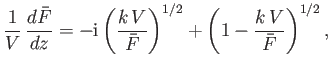
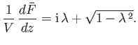
Hence,
 |
(6.94) |
where, with cuts in the
-plane at  and
and  , the correct branch of
 is that which is real and
positive when
is that which is real and
positive when
 . Integration, with the aid of Equation (6.92), yields
![$\displaystyle \frac{\pi}{2}\,\frac{V}{\skew{3}\bar{\psi}_1}\,(z-z_1)= {\rm i}\,(\lambda-1)-(1-\lambda^{\,2})^{1/2}+\tanh^{-1}[(1-\lambda^{\,2})^{1/2}],$](img2211.png) |
(6.95) |
where  is a constant. However,
  at the point
  , where
 (
( being the width of the orifice),
so
being the width of the orifice),
so
 , and
, and
![$\displaystyle \frac{\pi}{2}\,\frac{V}{\skew{3}\bar{\psi}_1}\,(z-{\rm i}\,d)= {\rm i}\,(\lambda-1)-(1-\lambda^{\,2})^{1/2}+\tanh^{-1}[(1-\lambda^{\,2})^{1/2}],$](img2216.png) |
(6.96) |
Finally, the required relationship between
and
is obtained by eliminating
between Equations (6.92) and (6.96).
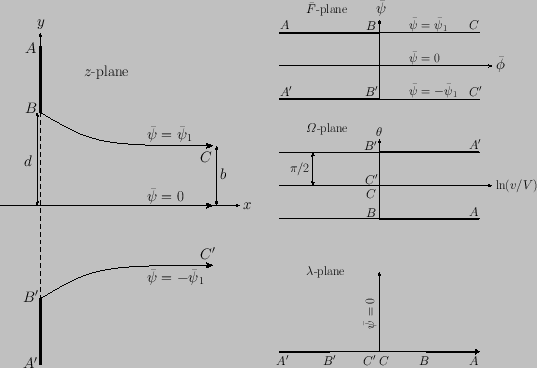
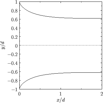
Figure 6.16:
Free streamlines of a liquid jet emerging from an orifice in a plane wall in two dimensions.
 |
On the free streamline  , we have
where  denotes distance measured along the streamline from
. It follows from Equations (6.91) and (6.92) that
denotes distance measured along the streamline from
. It follows from Equations (6.91) and (6.92) that
 |
(6.98) |
Thus, making use of Equation (6.96), the equation of streamline
can be written, in parametric form, as
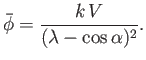
Thus, the asymptotic semi-width of the jet is
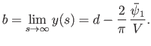 |
(6.101) |
Far from the orifice, which corresponds to
 , Equation (6.94) yields
 |
(6.102) |
In other words, as expected, the velocity profile becomes uniform across the jet far downstream of the orifice, which implies that
 . It follows, from Equation (6.101), that the contraction ratio of a two-dimensional liquid jet emerging from
an orifice in a plane wall takes the value
. It follows, from Equation (6.101), that the contraction ratio of a two-dimensional liquid jet emerging from
an orifice in a plane wall takes the value
 |
(6.103) |
Somewhat surprisingly, this value is very close to the observed contraction ratio of a three-dimensional jet emerging from a circular hole in a plane wall. (See Section 4.6.)
According to Equations (6.99), (6.100), and (6.103), the equation of the free streamline
can be written
for
 . By symmetry, the equation of the free streamline
  is obtained from the previous equation via
the transformation
is obtained from the previous equation via
the transformation
 ,
,
 . The streamlines
and
are plotted in Figure 6.16.
. The streamlines
and
are plotted in Figure 6.16.
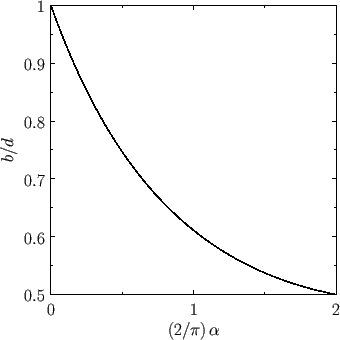
Figure:
Contraction ratio of a liquid jet emerging from a two-dimensional orifice formed by a gap between two semi-infinite plane walls that subtend an angle  .
.
 |
We can easily extend the previous calculation to determine the contraction ratio of a liquid jet emerging from
a two-dimensional orifice formed by a gap between two semi-infinite plane walls that subtend an angle
.
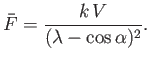
In this case, the free streamline
, on which
, corresponds to  and
and
 , whereas the free streamline
,
on which
,
corresponds to
and
, whereas the free streamline
,
on which
,
corresponds to
and
 . Hence, the transformation (6.93) generalizes to give
 |
(6.106) |
which implies that
![$\displaystyle V\,\frac{dz}{d\bar{F}} = \left[-{\rm i}\,\lambda + (1-\lambda^{\,2})^{1/2}\right]^{\,2\,\alpha/\pi}.$](img2243.png) |
(6.107) |
Far from the orifice, which corresponds to
, the previous expression yields
 . In other words, a long way
downstream of the orifice, the velocity
profile is again uniform across the jet. Hence, we can write
, where
. In other words, a long way
downstream of the orifice, the velocity
profile is again uniform across the jet. Hence, we can write
, where  is the semi-width of the jet far
from the orifice. Combining the previous two equations, we obtain
is the semi-width of the jet far
from the orifice. Combining the previous two equations, we obtain
![$\displaystyle -\frac{\pi}{2}\,\frac{dz}{b}=\frac{d\lambda}{\lambda} \left[-{\rm i}\,\lambda + (1-\lambda^{\,2})^{1/2}\right]^{\,2\,\alpha/\pi}.$](img2245.png) |
(6.108) |
Now,
corresponds to the point
, at which
, where  is the semi-width of the orifice.
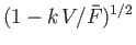
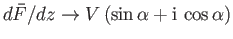
Thus, integration of the previous expression yields
is the semi-width of the orifice.
Thus, integration of the previous expression yields
![$\displaystyle \frac{z-{\rm i}\,d}{b} = \frac{2}{\pi}\int_\lambda^1 \frac{dk}{k}\left[-{\rm i}\,k + (1-k^{\,2})^{1/2}\right]^{\,2\,\alpha/\pi}.$](img2246.png) |
(6.109) |
Making the transformation
 , we get
 |
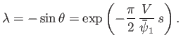
(6.110) |
As before, we have
![$ \lambda = \exp[-(\pi/2)\,(s/b)]$](img2249.png) on the free streamline
, where
denotes distance measured along the streamline from
.
Far downstream of the orifice,
and
on the free streamline
, where
denotes distance measured along the streamline from
.
Far downstream of the orifice,
and
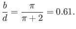
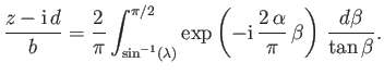
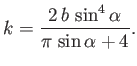
 . Hence, we obtain the following expression for the contraction ratio of the jet:
![$\displaystyle \frac{b}{d} =\left(1+\frac{2}{\pi}\int_0^{\pi/2}\frac{\sin[(2\,\alpha/\pi)\,\beta]}{\tan\beta}\,d\beta\right)^{-1}.$](img2251.png) |
(6.111) |
This contraction ratio is plotted as a function of  in Figure 6.17. It can be seen that the ratio takes the value
  when
when  , which corresponds to a two-dimensional jet emerging from a gap between two parallel planes. Not surprisingly, there is
no contraction in this case, because the streamlines of the flow are already parallel before they emerge from the orifice. On the
other hand, the ratio takes the value
, which corresponds to a two-dimensional jet emerging from a gap between two parallel planes. Not surprisingly, there is
no contraction in this case, because the streamlines of the flow are already parallel before they emerge from the orifice. On the
other hand, the ratio takes the value  when
when
 , which corresponds to the two-dimensional equivalent to the
Borda mouthpiece discussed in Section 4.6. In this case, the contraction ratio is exactly the same as that of a three-dimensional
Borda mouthpiece, which is not surprising, because there is nothing in the discussion of Section 4.6 that depends crucially on the
shape of the mouthpiece cross-section.
, which corresponds to the two-dimensional equivalent to the
Borda mouthpiece discussed in Section 4.6. In this case, the contraction ratio is exactly the same as that of a three-dimensional
Borda mouthpiece, which is not surprising, because there is nothing in the discussion of Section 4.6 that depends crucially on the
shape of the mouthpiece cross-section.
Figure 6.18:
Conformal transformations required for the determination of the flow past a flat plate with a cavity at ambient pressure.
 |
As a second example of the use of free streamline theory, consider the flow past a flat plate normal to a liquid stream of infinite extent. The
pressure in the cavity formed behind the plate is assumed to be equal to that of the undisturbed stream. Thus, the speed of the liquid
on the free streamlines bounding the cavity is equal to
, which is the uniform flow speed far upstream of the plate. Let us take
on the central streamline that divides at the stagnation point  , and later becomes the two
free streamlines. (See Figure 6.18.)
, and later becomes the two
free streamlines. (See Figure 6.18.)
The correspondence between the various points on the streamline
in the
-,
-, and
-planes
is specified in Figure 6.18. The flow occupies the whole of the
-plane, apart from a thin slit running along the positive section
of the real axis. As previously, the procedure is to find transformations that map the flow regions in both the
- and
-planes
coincidentally onto the upper half of the
-plane. The semi-infinite strip in the
-plane has the same
width, position, and orientation as that shown in Figure 6.15. Thus, the appropriate relationship between
and
is again
 |
(6.112) |
with the locations of the points
and  again being
 and
and
 , respectively.
The appropriate relationship between
and
can be recognized by noting, first, that the flow occupies the
upper half of the
, respectively.
The appropriate relationship between
and
can be recognized by noting, first, that the flow occupies the
upper half of the
 -plane, and, second, that an inversion and change of sign are needed to
bring corresponding points on the two real axes into coincidence. Thus, we obtain
-plane, and, second, that an inversion and change of sign are needed to
bring corresponding points on the two real axes into coincidence. Thus, we obtain
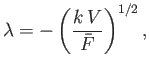 |
(6.113) |
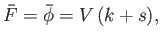
where  is some positive constant.
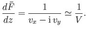
The required relation between
and
is given by
 |
(6.114) |
Hence,
 |
(6.115) |
where the relevant branch of
 is that which is positive on
  .
Integration, making use of the fact that
.
Integration, making use of the fact that  when
when  , yields
![$\displaystyle \frac{z}{k}=\int_0^{\bar{F}/k\,V}\frac{du}{-{\rm i}\,u^{\,-1/2}+(...
...{1/2}}=\int_0^{\bar{F}/k\,V}\left[\,{\rm i}\,u^{\,-1/2}+(1-1/u)^{1/2}\right]du,$](img2265.png) |
(6.116) |
or
![$\displaystyle \frac{z}{k} = \left(\frac{\bar{F}}{k\,V}\right)^{1/2}\left(\frac{...
...ight]+2\,{\rm i}\left(\frac{\bar{F}}{k\,V}\right)^{1/2}+{\rm i}\,\frac{\pi}{2}.$](img2266.png) |
(6.117) |
We can now evaluate the constant
making use of the fact that at the point
, where
,
 |
|
 |
(6.118) |
Here,
is the semi-width of the plate. Thus, we obtain
 |
(6.119) |
On the free streamline
,
 |
|
 |
(6.120) |
where
represents distance along the streamline measured from
. Thus, on this streamline,
 |
(6.121) |
Hence, according to Equation (6.117), the equation of the streamline
can be written, in parametric form, as
By symmetry, the equation of the free streamline
is obtained from the previous equation via
the transformation
,
.
We deduce that the cavity downstream of the plate extends to infinity, and that its boundary asymptotes to the parabola
 |
(6.124) |
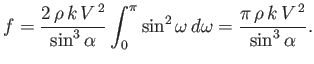
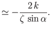
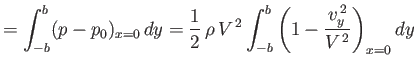
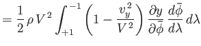
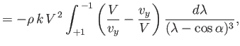
From Bernoulli's theorem, the net force per unit length exerted by the fluid on the plate, which is
obviously normal to the plate, and, therefore, directed parallel to the
-axis, is
In conventional parlance, this force constitutes a drag, because it is directed parallel to the undisturbed flow. (See Section 5.8.)
Now,
 on
on  , so
, so
 |
(6.127) |
where
 .
However,
.
However,
 .
Hence,
.
Hence,
![$\displaystyle D= \rho\,V^{\,2}\,b-\rho\, V^{\,2}\,k\int_0^1\left[\frac{1}{\gamma^{1/2}}-\left(\frac{1}{\gamma}-1\right)^{1/2}\right]d\gamma,$](img2283.png) |
(6.128) |
which yields
 |
(6.129) |
Finally, if we define the drag coefficient, in the conventional manner (see Section 8.8), then
we obtain
 |
(6.130) |
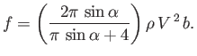
We can extend the previous calculation to determine the flow past a flat plate inclined at an angle
to a liquid
stream of infinite extent. Let the plate lie in the plane  . The flow field then occupies a semi-infinite strip in the
-plane
that has the same width, position, and orientation as that in the previous calculation. Consequently, the appropriate relation between
and
is again
. The flow field then occupies a semi-infinite strip in the
-plane
that has the same width, position, and orientation as that in the previous calculation. Consequently, the appropriate relation between
and
is again
 |
(6.131) |
It follows that
 |
(6.132) |
As before, the two edges of the plate,
and
, correspond to
and
, respectively. Furthermore, the
stagnation point,
, on the front surface of the plate corresponds to
 . (See Figure 6.18.) However, the latter point is no longer
necessarily located at the plate's midpoint.
. (See Figure 6.18.) However, the latter point is no longer
necessarily located at the plate's midpoint.
The transformation (6.113) generalizes to give
 |
(6.133) |
At the points
,
, and
,
 and, hence,
 . (See Figure 6.18.)
It follows from Equation (6.132)
that
. (See Figure 6.18.)
It follows from Equation (6.132)
that
 , which implies that
 and
and
 .
In other words, far upstream and downstream of the plate, the fluid velocity vector subtends an angle
with the plane
.
.
In other words, far upstream and downstream of the plate, the fluid velocity vector subtends an angle
with the plane
.
On the front surface of the plate,  ,
,
 and
and
 . Hence,
from Equation (6.132),
. Hence,
from Equation (6.132),
 |
(6.134) |
where the upper/lower signs correspond to  and
and  , respectively. (The signs are chosen to ensure that
 as
.) Moreover,
as
.) Moreover,
 on
, so
Equation (6.133) implies that
on
, so
Equation (6.133) implies that
 |
(6.135) |
It follows that
 |
(6.136) |
Writing
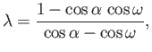 |
(6.137) |
the points
,
, and
correspond to  ,
,
 , and
, and
 , respectively. Furthermore,
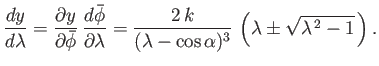
Hence, Equations (6.136)-(6.139) yield
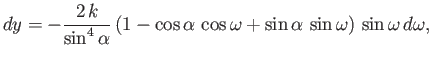 |
(6.140) |
which can be integrated to give
![$\displaystyle y = \frac{k}{\sin^4\alpha}\left[2\,\cos\omega+\cos\alpha\,\sin^2\...
...pha\,\sin\omega\,\cos\omega+\sin\alpha\left(\frac{\pi}{2}-\omega\right)\right],$](img2313.png) |
(6.141) |
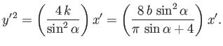
where we have chosen the constant of integration so as to ensure that the midpoint of the plate lies at  . We expect
  when
,
where
is the semi-width of the plate. We, thus, deduce, from the previous expression, that
when
,
where
is the semi-width of the plate. We, thus, deduce, from the previous expression, that
 |
(6.142) |
In particular, the stagnation point,
, at which
, lies a distance
![$\displaystyle y(\alpha)= \frac{2\,b}{\pi\,\sin\alpha+4}\left[2\,\cos\alpha\,(1+\sin^2\alpha)+\sin\alpha\left(\frac{\pi}{2}-\alpha\right)\right]$](img2316.png) |
(6.143) |
from the plate's midpoint.
Suppose that
 |
(6.144) |
where
 . It follows, from Equation (6.133), that
 |
(6.145) |
and, from Equation (6.132), that
 |
(6.146) |
where
 . Here,
  and
and  are Cartesian coordinates oriented such that the unperturbed flow is
parallel to the
-axis.
The previous two expressions can be combined to give
are Cartesian coordinates oriented such that the unperturbed flow is
parallel to the
-axis.
The previous two expressions can be combined to give
 |
(6.147) |
Now,  is real and negative on the free streamline
, and real and positive on the free streamline
. (See Figure 6.18.)
We conclude that, in the small-
is real and negative on the free streamline
, and real and positive on the free streamline
. (See Figure 6.18.)
We conclude that, in the small- limit, the equations of these streamlines can be written, in parametric form, as
In other words, far downstream of the plate, the free streamlines, which form the boundaries of the cavity behind the plate, asymptote to the parabola
 |
(6.150) |
From Bernoulli's theorem, the net force per unit length exerted by the fluid on the plate, which is
obviously normal to the plate, and, therefore, directed parallel to the
-axis, is
where use has been made of Equation (6.135).
However, according to Equations (6.134) and (6.139),
 |
(6.152) |
Thus, making use of Equation (6.138), we obtain
 |
(6.153) |
Hence, it follows from Equation (6.142) that
 |
(6.154) |
The drag,  , is the component of the force acting on the plate in the direction of the unperturbed flow: that is,
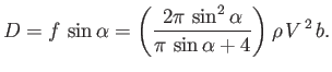 |
(6.155) |
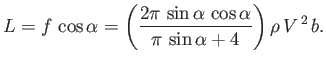
On the other hand, the lift,  , is the component of the force acting perpendicular to the direction of the unperturbed flow. (See Section 5.8.)
Thus,
, is the component of the force acting perpendicular to the direction of the unperturbed flow. (See Section 5.8.)
Thus,
 |
(6.156) |
Finally, it can be seen, from a comparison between Equations (6.124), (6.129), (6.150), and (6.155), that
there appears to be a connection between the drag force exerted on the plate, and the shape of the parabola to which the cavity formed
behind the plate asymptotes. In fact,
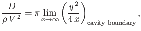 |
(6.157) |
where the unperturbed flow runs parallel to the
-axis. It turns out that this relation is a general one for two-dimensional flow
past a body of arbitrary shape with an attached cavity at ambient pressure (Batchelor 2000).
Next: Complex Line Integrals
Up: Two-Dimensional Potential Flow
Previous: Schwarz-Christoffel Theorem
Richard Fitzpatrick
2016-01-22
![$\displaystyle =\frac{2}{\pi+2}\left[\tanh^{-1}(\cos\zeta)-\cos\zeta)\right],$](img2231.png)
![$\displaystyle =(k+s)^{1/2}\,s^{1/2} -k\ln\left[\left(1+\frac{s}{k}\right)^{1/2}+\left(\frac{s}{k}\right)^{1/2}\right],$](img2272.png)

![$\displaystyle =\frac{2}{\pi}\,\frac{\skew{3}\bar{\psi}_1}{V}\left[\tanh^{-1}(\cos\theta)-\cos\theta)\right],$](img2223.png)