Multi-Slit Interference
Suppose that the interference apparatus pictured in Figure 10.1 is modified such that  identical slits of width
 ,
running parallel to the
,
running parallel to the  -axis, are cut in the
opaque screen that occupies the plane
-axis, are cut in the
opaque screen that occupies the plane  . Let the slits be located at
  , for
, for  . For the sake of
simplicity, the arrangement of slits is assumed to
be symmetric with respect to the plane
. For the sake of
simplicity, the arrangement of slits is assumed to
be symmetric with respect to the plane  . In other words, if there is a slit at then there is also
a slit at
. In other words, if there is a slit at then there is also
a slit at  .
The distance between the
.
The distance between the  th slit and a
point on the projection screen that is an angular distance
th slit and a
point on the projection screen that is an angular distance  from the plane
is [cf., Equation (10.3)]
from the plane
is [cf., Equation (10.3)]
![$\displaystyle \rho_n = R\left[1-\frac{x_n}{R}\,\sin\theta + {\cal O}\left(\frac{x_n^{\,2}}{R^{\,2}}\right)\right].$](img3369.png) |
(10.31) |
Thus, making use of the far-field
orderings (10.10), where  now represents the typical spacing between neighboring slits,
and assuming normally incident collimated light, Equation (10.5) generalizes to
now represents the typical spacing between neighboring slits,
and assuming normally incident collimated light, Equation (10.5) generalizes to
 |
(10.32) |
which can also be written
 |
(10.33) |
 |
(10.34) |
Here, we have made use of the fact that arrangement of slits is symmetric with respect to the plane
[which implies that
 ]. We have also employed the trigonometrical
identity
]. We have also employed the trigonometrical
identity
 . (See Appendix B.)
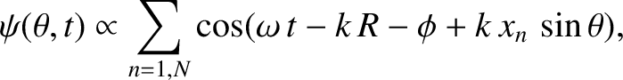
It follows that the intensity of
the interference pattern appearing on the projection screen is specified by
. (See Appendix B.)
It follows that the intensity of
the interference pattern appearing on the projection screen is specified by
![$\displaystyle {\cal I}(\theta) \propto \langle \psi^{\,2}(\theta,t)\rangle \pro...
...um_{n=1,N} \cos\left(2\pi\,\frac{x_n}{\lambda}\,\sin\theta\right)\right]^{\,2},$](img3374.png) |
(10.35) |
because
 .
The previous expression is a generalization of Equation (10.12).
.
The previous expression is a generalization of Equation (10.12).
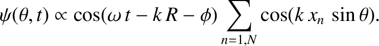
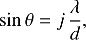
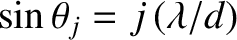
Figure 10.8:
Multi-slit far-field interference pattern calculated for  and
and
 with normal
incidence and narrow slits.
with normal
incidence and narrow slits.
|
|
Suppose that the slits are evenly spaced a distance apart, so that
![$\displaystyle x_n = [n-(N+1)/2]\,d$](img3376.png) |
(10.36) |
for . It follows that
![$\displaystyle {\cal I}(\theta) \propto \left[\sum_{n=1,N} \cos\left(2\pi\,[n-(N+1)/2]\,\frac{d}{\lambda}\,\sin\theta\right)\right]^{\,2},$](img3377.png) |
(10.37) |
which can be summed to give
![$\displaystyle {\cal I}(\theta)\propto \frac{\sin^2[\pi\,N\,(d/\lambda)\,\sin\theta]}{\sin^2[\pi\,(d/\lambda)\,\sin\theta)]}.$](img3378.png) |
(10.38) |
(See Exercise 1.)
The multi-slit interference function, (10.38), exhibits strong maxima in situations in which
its numerator and denominator are simultaneously zero; that is, when
 |
(10.39) |
where
 is an integer. In this situation, application of l'Hopital's rule yields
 . The
heights of these so-called principal maxima in the interference function are very large, being proportional to
. The
heights of these so-called principal maxima in the interference function are very large, being proportional to  , because
there is constructive
interference of the light from all slits. This occurs because the distances between neighboring
slits and the point on the projection screen at which a given maximum is located differ by an integer number of wavelengths; that is,
, because
there is constructive
interference of the light from all slits. This occurs because the distances between neighboring
slits and the point on the projection screen at which a given maximum is located differ by an integer number of wavelengths; that is,
 . All of the principal maxima have the same height.
The multi-slit interference function (10.38) is zero when
its numerator is zero, but its denominator non-zero; that is, when
 |
(10.40) |
where
 is an integer that is not an integer multiple of . It follows that there are
  zeros between neighboring
principal maxima. It can also be demonstrated that there are
zeros between neighboring
principal maxima. It can also be demonstrated that there are  secondary maxima between
neighboring principal maxima. However, these maxima are much lower in height, by a factor of order , than the primary maxima.
secondary maxima between
neighboring principal maxima. However, these maxima are much lower in height, by a factor of order , than the primary maxima.
Figure 10.8 shows the typical far-field interference pattern produced by a system of ten identical,
equally spaced, parallel slits, assuming normal incidence and narrow slits, when the slit spacing, , greatly exceeds the wavelength,  ,
of the light (which, as we saw in Section 10.2, is the most interesting case). It can be seen that the
pattern consists of a series of bright fringes of equal intensity, separated by much wider
(relatively) dark fringes. The bright fringes correspond to the principal maxima discussed previously. As is the case for two-slit interference, the innermost (i.e., low , small ) principal maxima are approximately equally spaced, with a characteristic angular
spacing
,
of the light (which, as we saw in Section 10.2, is the most interesting case). It can be seen that the
pattern consists of a series of bright fringes of equal intensity, separated by much wider
(relatively) dark fringes. The bright fringes correspond to the principal maxima discussed previously. As is the case for two-slit interference, the innermost (i.e., low , small ) principal maxima are approximately equally spaced, with a characteristic angular
spacing
 . [This
result follows from Equation (10.39), and the small-angle approximation
. [This
result follows from Equation (10.39), and the small-angle approximation
 .] However, the typical angular width of a principal maximum
(i.e., the angular distance between the maximum and the closest zeroes on either side of it) is
.] However, the typical angular width of a principal maximum
(i.e., the angular distance between the maximum and the closest zeroes on either side of it) is
 . [This result follows from Equation (10.40), and the small-angle approximation.] The ratio of the angular width of a principal maximum to the angular spacing between successive maxima is thus
 |
(10.41) |
Hence, we conclude that, as the number of slits increases, the bright fringes in a multi-slit interference pattern become progressively sharper.
The most common practical application of multi-slit interference is the transmission diffraction grating. Such a device consists
of identical, equally spaced, parallel scratches on one side of a thin uniform transparent glass, or plastic, film. When the film is illuminated, the scratches
strongly scatter the incident light, and effectively constitute identical, equally spaced, parallel line sources. Hence, the grating generates
the type of -slit interference pattern discussed previously, with one major difference. Namely, the central ( ) principal maximum has
contributions not only from the scratches, but also from all the transparent material between the scratches. Thus, the central
principal maximum is considerably brighter than the other (
) principal maximum has
contributions not only from the scratches, but also from all the transparent material between the scratches. Thus, the central
principal maximum is considerably brighter than the other ( ) principal maxima.
Diffraction gratings are often employed in spectroscopes, which are instruments used to decompose light that is
made up of a mixture of different wavelengths into its
constituent wavelengths. As a simple example, suppose that a spectroscope contains an -line diffraction grating that is illuminated, at normal incidence,
by a mixture of light of wavelength , and light of wavelength
 , where
 . As always, the overall interference pattern (i.e., the overall wavefunction at the projection screen) produced by the grating is a linear superposition
of the pattern generated by the light of wavelength , and the pattern generated by the
light of wavelength
. Consider the th-order principal maximum associated
with the wavelength interference pattern, which is located at
. As always, the overall interference pattern (i.e., the overall wavefunction at the projection screen) produced by the grating is a linear superposition
of the pattern generated by the light of wavelength , and the pattern generated by the
light of wavelength
. Consider the th-order principal maximum associated
with the wavelength interference pattern, which is located at  , where
 . [See Equation (10.39).] Here, is
the spacing between neighboring lines on the diffraction grating, which is assumed to be greater than . (Incidentally, the
width of the lines is assumed to be much less than .)
The maximum in question has a finite angular width.
We can determine this width by locating the zeros in the interference pattern on either side of the maximum. Let the zeros
be
located at
. [See Equation (10.39).] Here, is
the spacing between neighboring lines on the diffraction grating, which is assumed to be greater than . (Incidentally, the
width of the lines is assumed to be much less than .)
The maximum in question has a finite angular width.
We can determine this width by locating the zeros in the interference pattern on either side of the maximum. Let the zeros
be
located at
 .
The maximum itself corresponds to
.
The maximum itself corresponds to
 . Hence, the
zeros correspond to
. Hence, the
zeros correspond to
 (i.e.,
they correspond to the first zeros of the function
(i.e.,
they correspond to the first zeros of the function
![$\sin[\pi\,N\,(d/\lambda)\,\sin\theta]$](img3396.png) on either side of the zero at .) [See Equation (10.38).]
Taylor expanding to first order in
on either side of the zero at .) [See Equation (10.38).]
Taylor expanding to first order in
 , we obtain
 |
(10.42) |
Hence, the maximum in question effectively extends from
 to
to
 .
Consider the th-order principal maximum associated with the wavelength
interference pattern, which is
located at
.
Consider the th-order principal maximum associated with the wavelength
interference pattern, which is
located at
 , where
 . [See Equation (10.39).] Taylor
expanding to first order in
. [See Equation (10.39).] Taylor
expanding to first order in
 , we obtain
 |
(10.43) |
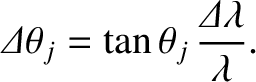
In order for the spectroscope to resolve the incident light into its two constituent wavelengths, at the th spectral order, the angular spacing,
, between the
th-order maxima associated with these two wavelengths must be greater than the angular widths,
, of the
maxima themselves. If this is the case then the overall th-order maximum will consist of two closely spaced maxima, or “spectral lines” (centered at and
). On the other hand, if this is not the case then the two maxima will merge to form a single maximum, and it will
consequently not be possible to tell that the incident light consists of a mixture of two different wavelengths. Thus, the condition
for the spectroscope to be able to resolve the spectral lines at the th spectral order is
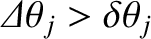 , or
, or
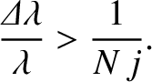 |
(10.44) |
We conclude that the resolving power of a diffraction grating spectroscope increases as the number of illuminated lines
(i.e., ) increases, and also as the spectral order (i.e., ) increases. Incidentally, there
is no resolving power at the lowest (i.e., ) spectral order, because the corresponding principal maximum is located at  irrespective of the wavelength of the incident light. Moreover, there is a limit to how large can become (i.e., a given diffraction
grating, illuminated by light of a given wavelength, has a finite number of principal maxima). This follows because
irrespective of the wavelength of the incident light. Moreover, there is a limit to how large can become (i.e., a given diffraction
grating, illuminated by light of a given wavelength, has a finite number of principal maxima). This follows because
 cannot
exceed unity, so, according to Equation (10.39), cannot exceed
cannot
exceed unity, so, according to Equation (10.39), cannot exceed  .
.
![\includegraphics[width=0.9\textwidth]{Chapter10/fig10_08.eps}](img3375.png)