Next: Bibliography Up: Neoclassical Tearing Modes Previous: Generalized Rutherford Equation Contents
 [37].
Second, the heating of the plasma due to the absorbed waves can locally decrease the plasma resistivity, leading to a local enhancement of the inductive toroidal
plasma current that offsets the destabilizing reduction in the bootstrap current consequent on the flattening of the pressure profile within the mode's magnetic separatrix
[15]. Third, the current driven by the absorbed waves can directly fill in the hole in the bootstrap current profile left by the flattening of the pressure profile within the sepatatrix
[15,38]. We shall concentrate on the third stabilization mechanism, which is the only practical one in a tokamak
fusion reactor.
[37].
Second, the heating of the plasma due to the absorbed waves can locally decrease the plasma resistivity, leading to a local enhancement of the inductive toroidal
plasma current that offsets the destabilizing reduction in the bootstrap current consequent on the flattening of the pressure profile within the mode's magnetic separatrix
[15]. Third, the current driven by the absorbed waves can directly fill in the hole in the bootstrap current profile left by the flattening of the pressure profile within the sepatatrix
[15,38]. We shall concentrate on the third stabilization mechanism, which is the only practical one in a tokamak
fusion reactor.
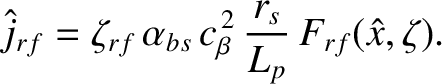
In the presence of rf-driven current, Equation (11.2) generalizes such that
 |
(12.27) |
 is the parallel current density generated by absorbed rf waves. If
 ,
where
,
where  is the equilibrium toroidal magnetic field-strength, then it is convenient to write
 |
(12.28) |
 is defined in Equation (11.10),
 , where
  is a radial cylindrical coordinate,
and
is a radial cylindrical coordinate,
and
 , where
  and
and  are poloidal and toroidal angles, respectively. Moreover,
 is the rf-driven current density profile, normalized such that the maximum value of
  is
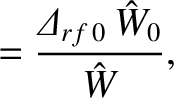
unity. Finally,
is
unity. Finally,
 is the ratio of the maximum rf-driven current density to the equilibrium bootstrap
current density at the rational surface.
is the ratio of the maximum rf-driven current density to the equilibrium bootstrap
current density at the rational surface.
In the presence of rf current drive, Equation (11.68) generalizes to give
 |
(12.29) |
 |
(12.30) |
 |
(12.32) |
 is defined in Section 8.6,
![$k=[(1+{\mit\Omega})/2]^{1/2}$](img2907.png) , and the
functions
, and the
functions
 and
and
 are defined in Section 8.11.
![\includegraphics[width=\textwidth]{Chapter12/Figure12_4.eps}](img3733.png) |
We can think of the dimensionless parameter  as a sort of
rf current drive efficiency. If
as a sort of
rf current drive efficiency. If
 then the destabilizing bootstrap term (i.e., the third term) on the right-hand side of the modified generalized Rutherford equation, (12.31), can be
completely suppressed (assuming that
then the destabilizing bootstrap term (i.e., the third term) on the right-hand side of the modified generalized Rutherford equation, (12.31), can be
completely suppressed (assuming that
 ) by driving a current density at the rational surface that matches the missing bootstrap current density (i.e.,
 ). In this case, the
rf current drive is 100% efficient at stabilizing the neoclassical tearing mode. On the other hand, if
). In this case, the
rf current drive is 100% efficient at stabilizing the neoclassical tearing mode. On the other hand, if
 then the destabilizing bootstrap term in the generalized Rutherford equation can only be
completely eliminated by driving a current density at the rational surface that is twice the missing bootstrap current density (i.e.,
then the destabilizing bootstrap term in the generalized Rutherford equation can only be
completely eliminated by driving a current density at the rational surface that is twice the missing bootstrap current density (i.e.,
 ).
In this case, the rf current drive is only 50% efficient.
).
In this case, the rf current drive is only 50% efficient.
![\includegraphics[width=\textwidth]{Chapter12/Figure12_5.eps}](img3739.png) |
Suppose that the normalized rf-driven current density profile is such that
![$\displaystyle F_{rf}(X,\zeta) =\exp\left[-\frac{(X-\delta_{rf})^2}{{\mit\Delta}...
...rf})<\zeta<\pi\,(1+\tau_{rf})\\ [0.5ex]
0&&\mbox{otherwise}
\end{array}\right.,$](img3740.png) |
(12.33) |
 .
In other words, the profile is a Gaussian, of full-width-half-maximum (in )
.
In other words, the profile is a Gaussian, of full-width-half-maximum (in )
 , that is centered on the magnetic flux-surface whose
minor radius is offset from that of the rational surface by
, that is centered on the magnetic flux-surface whose
minor radius is offset from that of the rational surface by
 . Moreover, the driven current is concentrated at the island chain O-points. The degree of
concentration is measured by the so-called duty cycle parameter,
. Moreover, the driven current is concentrated at the island chain O-points. The degree of
concentration is measured by the so-called duty cycle parameter,  . (
. (
 corresponds to no concentration, whereas
 corresponds
to complete concentration.) In practice, the concentration is achieved by modulating the rf power such that it is turned on each time an island O-point rotates past the
source, and turned off each time an island X-point rotates past the source. The duty cycle parameter, , is the fraction of time that the rf power is turned on.
corresponds
to complete concentration.) In practice, the concentration is achieved by modulating the rf power such that it is turned on each time an island O-point rotates past the
source, and turned off each time an island X-point rotates past the source. The duty cycle parameter, , is the fraction of time that the rf power is turned on.
It is easily demonstrated that
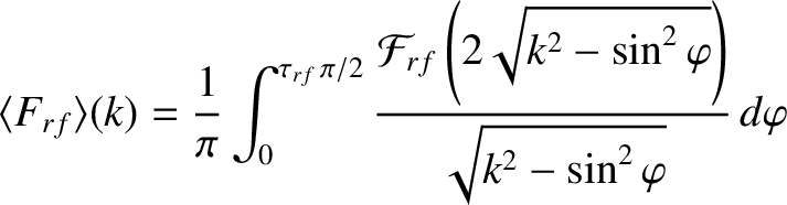 |
(12.34) |
 , and
, and
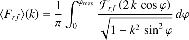 |
(12.35) |
 , where
 |
![$\displaystyle =\frac{1}{2}\left(\exp\left[-\frac{(X-\delta_{rf})^2}{{\mit\Delta...
...t]+ \exp\left[-\frac{(X+\delta_{rf})^2}{{\mit\Delta}_{rf}^{\,2}}\right]\right),$](img3750.png) |
(12.36) |
 |
(12.37) |
![\includegraphics[width=\textwidth]{Chapter12/Figure12_6.eps}](img3753.png) |
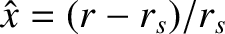
Figures 12.4 and 12.5 illustrate how the current drive efficiency parameter, , varies with the current drive profile width parameter,
 , and the
duty cycle parameter, , in cases where these is no misalignment between the current drive profile and the rational surface (i.e.,
, and the
duty cycle parameter, , in cases where these is no misalignment between the current drive profile and the rational surface (i.e.,
 ). It can be seen that
attains a maximum value of about
). It can be seen that
attains a maximum value of about  when
when
 and
and
 [28]. Thus, the optimal full-width-half-maximum of the
current drive profile is about 83% of the width of the magnetic island chain. It can also be seen that optimal modulation of the driven current increases the maximum achievable
current drive efficiency by about 50%, while reducing the required rf power by 40% [28].
[28]. Thus, the optimal full-width-half-maximum of the
current drive profile is about 83% of the width of the magnetic island chain. It can also be seen that optimal modulation of the driven current increases the maximum achievable
current drive efficiency by about 50%, while reducing the required rf power by 40% [28].
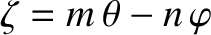
Figure 12.6 illustrates what happens when the current drive profile is misaligned with the rational
surface (i.e., when the peak driven current density does not lie on the rational surface). It can be seen that misalignment decreases the current drive efficiency. Indeed, if the misalignment
becomes too great then the efficiency becomes negative (indicating that the current drive destabilizes, rather than stabilizes, the neoclassical tearing mode) [28]. When
, the maximum tolerable misalignment is about
 , which corresponds to a misalignment in minor radius of about 63% of the island width [28].
The broad conclusion that can be drawn from Figures 12.4–12.5 is that the maximum current drive efficiency is achieved when the driven current profile matches the profile of the missing bootstrap current (i.e., when it is centered on the rational surface, is of radial extent of about an island width, and is slightly concentrated at the island O-points).
![\includegraphics[width=\textwidth]{Chapter12/Figure12_7.eps}](img3758.png) |
Consider a neoclassical tearing mode for which the right-hand side of the generalized Rutherford equation case is specified in Figure 12.3. Suppose that the magnetic island chain has achieved its final steady-state width,
 . Let us apply an rf current drive profile
whose width and misalignment parameters are
. Let us apply an rf current drive profile
whose width and misalignment parameters are
 and
and
 , respectively. The applied current drive causes the island chain to shrink in width.
Assuming that the current drive profile remains constant, the effective
width and misalignment parameters when the normalized island width has shrunk to the value
, respectively. The applied current drive causes the island chain to shrink in width.
Assuming that the current drive profile remains constant, the effective
width and misalignment parameters when the normalized island width has shrunk to the value  are
are
 |
 |
(12.38) |
 |
 |
(12.39) |
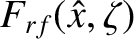
Figure 12.7 shows how the right-hand side of the generalized Rutherford equation specified in Figure 12.3 is modified by an rf current drive profile with optimal width,
 (i.e., a full-width-half-maximum of 9.2% of the plasma minor radius), optimal
alignment,
(i.e., a full-width-half-maximum of 9.2% of the plasma minor radius), optimal
alignment,
 , and optimal duty cycle,
 . It can be seen that the neoclassical tearing mode is completely stabilized [i.e.,
 for all ]
once the peak amplitude of the driven current density exceeds 75% of the equilibrium bootstrap current density at the rational surface (i.e.,
for all ]
once the peak amplitude of the driven current density exceeds 75% of the equilibrium bootstrap current density at the rational surface (i.e.,
 ). Of course, as soon as the island width has shrunk to value
less than the seed island width shown in Figure 12.3 (i.e.,
). Of course, as soon as the island width has shrunk to value
less than the seed island width shown in Figure 12.3 (i.e.,
 ), the rf power can be switched off, and the neoclassical tearing mode will not return (unless it
is triggered again by a transient resonant magnetic perturbation).
), the rf power can be switched off, and the neoclassical tearing mode will not return (unless it
is triggered again by a transient resonant magnetic perturbation).
![\includegraphics[width=\textwidth]{Chapter12/Figure12_8.eps}](img3771.png) |
Figure 12.8 shows how the right-hand side of the generalized Rutherford equation specified in Figure 12.3 is modified by an unmodulated (i.e.,
) rf current drive profile with optimal width,
, and optimal alignment,
. It can be seen that the neoclassical tearing mode is completely stabilized once
peak amplitude of the driven current density exceeds 291% of the equilibrium bootstrap current density at the rational surface (i.e.,
 ). The large increase in the requisite
driven current density, relative to the modulated case shown in Figure 12.7, comes about because unmodulated current drive becomes very inefficient at stabilizing a
neoclassical tearing mode once the island width shrinks to such an extent that it is much less than the current drive profile width. In other words,
). The large increase in the requisite
driven current density, relative to the modulated case shown in Figure 12.7, comes about because unmodulated current drive becomes very inefficient at stabilizing a
neoclassical tearing mode once the island width shrinks to such an extent that it is much less than the current drive profile width. In other words,
 as
as
 for
unmodulated current drive, whereas remains finite as
for modulated current drive [21,31].
To be more specific, for the case of unmodulated current drive, the stabilizing effect of the current driven at the island O-points is partially cancelled by the destabilizing effect of the current
driven at the island X-points [29]. This cancellation becomes almost exact when the island width is much less than the current drive profile width [21]. Of course, there is
no such cancellation in the case of modulated current drive because no current is driven at the X-points.
for
unmodulated current drive, whereas remains finite as
for modulated current drive [21,31].
To be more specific, for the case of unmodulated current drive, the stabilizing effect of the current driven at the island O-points is partially cancelled by the destabilizing effect of the current
driven at the island X-points [29]. This cancellation becomes almost exact when the island width is much less than the current drive profile width [21]. Of course, there is
no such cancellation in the case of modulated current drive because no current is driven at the X-points.
![\includegraphics[width=\textwidth]{Chapter12/Figure12_9.eps}](img3775.png) |
Figure 12.9 shows how the right-hand side of the generalized Rutherford equation specified in Figure 12.3 is modified by an rf current drive profile with optimal width,
, non-optimal
alignment,
 , and optimal duty cycle,
. It can be seen that the misalignment of the current drive profile causes the critical peak current density required
to stabilize the neoclassical tearing mode to rise to 261% of the equilibrium bootstrap current density at the rational surface.
, and optimal duty cycle,
. It can be seen that the misalignment of the current drive profile causes the critical peak current density required
to stabilize the neoclassical tearing mode to rise to 261% of the equilibrium bootstrap current density at the rational surface.
The broad conclusion that can be drawn from Figures 12.7–12.9 is that a neoclassical tearing mode can be stabilized by properly aligned, modulated, current drive in which the driven current density profile has a similar width to the magnetic island chain, and a similar peak magnitude to the equilibrium bootstrap current density at the rational surface.
Finally, successful stabilization of neoclassical tearing modes via electron cyclotron wave current drive has been achieved in many tokamak experiments, including ASDEX Upgrade [39], DIII-D [22], and JT-60U [25].