


Next: Antenna Arrays
Up: Radiation and Scattering
Previous: Basic Antenna Theory
We have seen that standard antennas emit more radiation in some directions
than in others. Indeed, it is topologically impossible for an antenna
to emit transverse waves uniformly in all directions
(for the same reason that it is impossible to comb the hair on a sphere
in such a manner
that there is no parting). One of the aims of antenna engineering
is to design antennas that transmit most of their radiation in a
particular direction. By a reciprocity argument, such an antenna, when
used as a receiver, is preferentially sensitive to radiation incident
from the same direction.
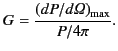
The directivity or gain of an antenna is defined as the ratio
of the maximum value of the power radiated per unit solid angle to
the average power radiated per unit solid angle: that is,
 |
(1242) |
Thus, the directivity measures how much more intensely the antenna
radiates in its preferred direction than a mythical ``isotropic
radiator'' would when fed with the same total power. For a Hertzian
dipole, the gain is  . For a half-wave antenna, the gain is
 . To achieve a directivity that is significantly greater than
unity, the antenna size needs to be much
larger than the wavelength. This is
usually achieved using a phased array of half-wave, or full-wave, antennas.
. To achieve a directivity that is significantly greater than
unity, the antenna size needs to be much
larger than the wavelength. This is
usually achieved using a phased array of half-wave, or full-wave, antennas.
Antennas can be used to receive, as well
as emit, electromagnetic radiation. The incoming wave
induces a voltage that can be detected in an electrical
circuit
connected to the antenna. In fact, this process is equivalent to the emission
of electromagnetic waves by the antenna viewed in reverse.
In the theory of electrical circuits, a receiving antenna is represented
as an emf connected
in series with a resistor. The emf,
 , represents
the voltage induced in the antenna by the incoming wave. The resistor,
, represents
the voltage induced in the antenna by the incoming wave. The resistor,
 , represents the power re-radiated by the antenna (here,
the real resistance
of the antenna is neglected). Let us represent the detector circuit as a single
load resistor
, represents the power re-radiated by the antenna (here,
the real resistance
of the antenna is neglected). Let us represent the detector circuit as a single
load resistor
 connected in series with the antenna.
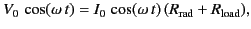
How can we choose
such that the maximum power is extracted from the
incoming wave and transmitted to the load resistor? According to Ohm's law,
connected in series with the antenna.
How can we choose
such that the maximum power is extracted from the
incoming wave and transmitted to the load resistor? According to Ohm's law,
 |
(1243) |
where
 is the current induced in the circuit.
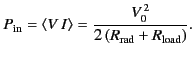
The power input to the circuit is
is the current induced in the circuit.
The power input to the circuit is
 |
(1244) |
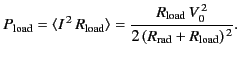
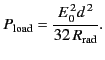
The power transferred to the load is
 |
(1245) |
Finally, the power re-radiated by the antenna is
 |
(1246) |
Note that
 .
The maximum power transfer to the load occurs when
.
The maximum power transfer to the load occurs when
![$\displaystyle \frac{\partial P_{\rm load}}{\partial R_{\rm load}} = \frac{V_0^{...
...rac{R_{\rm load} - R_{\rm rad}}{(R_{\rm rad} + R_{\rm load})^{\,3}}\right] = 0.$](img2663.png) |
(1247) |
Thus, the maximum transfer rate corresponds to
 |
(1248) |
In other words, the resistance of the load circuit must match the radiation
resistance of the antenna.
For this optimum case,
 |
(1249) |
So, even in the optimum case, half
of the power absorbed by the antenna is immediately
re-radiated. If
 then more than half of the
absorbed power is re-radiated. Clearly, an antenna that
is receiving electromagnetic radiation is also emitting it.
This is how the BBC (allegedly) catch people who do not pay their television license fee in
the UK. They have vans that can detect the radiation emitted by
a TV aerial while it is in use (they can even tell which channel you are watching!).
then more than half of the
absorbed power is re-radiated. Clearly, an antenna that
is receiving electromagnetic radiation is also emitting it.
This is how the BBC (allegedly) catch people who do not pay their television license fee in
the UK. They have vans that can detect the radiation emitted by
a TV aerial while it is in use (they can even tell which channel you are watching!).
For a Hertzian dipole antenna interacting with an incoming wave whose electric
field has an amplitude  , we expect
 |
(1250) |
Here, we have used the fact that the wavelength of the radiation is much
longer
than the length of the antenna, and
that the relevant emf develops between the
two ends and the centre of the antenna.
We have also assumed that the antenna is
properly aligned (i.e.,
the radiation is incident perpendicular to the axis of the
antenna). The Poynting flux of the incoming wave is
 |
(1251) |
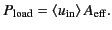
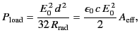
whereas the power transferred to a properly matched detector circuit is
 |
(1252) |
Consider an idealized antenna in which all
incoming radiation incident on some area
 is absorbed, and then
magically transferred to the detector circuit with no re-radiation.
Suppose that the power absorbed from the idealized antenna
matches that absorbed from
the
real antenna. This implies that
is absorbed, and then
magically transferred to the detector circuit with no re-radiation.
Suppose that the power absorbed from the idealized antenna
matches that absorbed from
the
real antenna. This implies that
 |
(1253) |
The quantity
, which is called the effective area
of an antenna, is
the area of the idealized antenna that absorbs as much net power from the incoming
wave as the actual antenna. Alternatively,
is the area of the
incoming wavefront that is captured by the receiving antenna and fed to
its load circuit.
Thus,
 |
(1254) |
giving
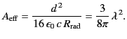 |
(1255) |
It is clear that the effective area of a Hertzian dipole antenna is of
order the wavelength squared of the incoming radiation.
We can generalize from this analysis of a special case. The
directivity of a Hertzian dipole is
. Thus, the effective area of
the isotropic radiator (the mythical reference antenna against which
directivities are measured) is
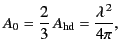 |
(1256) |
or
 |
(1257) |
where
 . Here, we have used the formal definition
of the effective area of an antenna:
is that area which, when
multiplied by the time-averaged Poynting flux of the incoming wave,
equals the maximum power received by the antenna (when its orientation
is optimal).
Clearly, the effective area of
an isotropic radiator is the same as the area of a circle whose radius is
the reduced wavelength,
. Here, we have used the formal definition
of the effective area of an antenna:
is that area which, when
multiplied by the time-averaged Poynting flux of the incoming wave,
equals the maximum power received by the antenna (when its orientation
is optimal).
Clearly, the effective area of
an isotropic radiator is the same as the area of a circle whose radius is
the reduced wavelength,
 .
.
We can take yet one more step, and conclude that the effective area of
any antenna of directivity  is
is
 |
(1258) |
Of course, to realize this full capture area, the antenna must be
orientated properly.
Let us calculated the coupling, or insertion loss, of an
antenna-to-antenna communications link. Suppose that a generator
delivers the power
 to a transmitting antenna, which is
aimed at a receiving antenna a distance
to a transmitting antenna, which is
aimed at a receiving antenna a distance  away. The (properly aligned) receiving
antenna then captures and delivers the power
away. The (properly aligned) receiving
antenna then captures and delivers the power
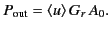
 to its load circuit. From the definition of
directivity, the transmitting antenna produces the time-averaged Poynting flux
to its load circuit. From the definition of
directivity, the transmitting antenna produces the time-averaged Poynting flux
 |
(1259) |
at the receiving antenna. The received power is
 |
(1260) |
Here,  is the gain of the transmitting antenna, and
  is
the gain of the receiving antenna.
Thus,
is
the gain of the receiving antenna.
Thus,
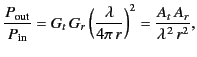 |
(1261) |
where  and
and  are the effective areas of the transmitting
and receiving antennas, respectively.
This result is known as the Friis transmission formula. Note that
the insertion loss depends on the product of the gains of the two antennas.
Thus, a properly aligned communications link has the same insertion
loss operating in either direction.
are the effective areas of the transmitting
and receiving antennas, respectively.
This result is known as the Friis transmission formula. Note that
the insertion loss depends on the product of the gains of the two antennas.
Thus, a properly aligned communications link has the same insertion
loss operating in either direction.
A thin wire linear antenna might appear to be essentially one-dimensional.
However, the concept of an effective area shows that it possesses a
second dimension determined by the wavelength. For instance, for a
half-wave antenna, the gain of which is
, the effective area
is
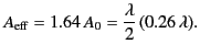 |
(1262) |
Thus, we can visualize the capture area as a rectangle that
is the physical length of the antenna in one direction, and
approximately one quarter of the wavelength in the other.
Next: Antenna Arrays
Up: Radiation and Scattering
Previous: Basic Antenna Theory
Richard Fitzpatrick
2014-06-27