


Next: Conformal Maps
Up: Two-Dimensional Potential Flow
Previous: Complex Velocity
Method of Images
Let
 and
and
 be complex
velocity potentials corresponding to distinct, two-dimensional, irrotational, incompressible flow patterns whose stream functions
are
 and
and
 , respectively. It follows that both stream functions satisfy Laplace's equation: that is,
 . Suppose that
 . Writing
 , it is clear
that
 . Moreover,
 , so
, so
 also satisfies Laplace's equation. We deduce that two complex velocity
potentials, corresponding to distinct, two-dimensional, irrotational, incompressible flow patterns, can be superposed to produce a third velocity
potential that corresponds to another
two-dimensional, irrotational, incompressible flow pattern. As described in the following, this idea can be exploited to determine the flow patterns produced by line sources and vortex filaments in the vicinity of rigid boundaries.
Figure 6.1:
Two line sources.
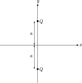 |
As an example, consider a situation in which there are two line sources of strength  located at the points
 . (See Figure 6.1.)
The complex velocity potential of the resulting flow pattern is the sum of the complex potentials of each source taken in isolation.
Hence, from Section 6.4,
 |
(6.42) |
Thus, the stream function of the flow pattern (which is the imaginary part of the complex potential) is
 |
(6.43) |
Note that
 , which implies that there is zero flow normal to the plane
  . Hence, in the region
  , we could interpret the
previous stream function as that generated by a single line source of strength
  , located at the point
  ,
,  ,
in the presence of a planar rigid boundary at
  . This follows because the stream
function satisfies
 everywhere in the region
  , has the requisite singularity (corresponding to a line source of strength
  ) at
) at  ,
,  , and
satisfies the physical boundary condition that the normal velocity be zero at the rigid boundary. Moreover,
as is well-known, the solutions of Laplace's equation are unique. The streamlines
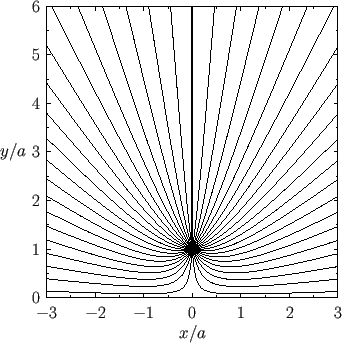
of the resulting flow pattern are shown in Figure 6.2. Incidentally, we can think of the two
sources in Figure 6.1 as the ``images'' of one another in the boundary plane. Hence, this method
of calculation is usually referred to as the method of images.
Figure:
Stream lines of the two-dimensional flow pattern due to a line source at  ,
,  in the presence
of a rigid boundary at
  .
.
 |
The complex velocity associated with the complex velocity potential (6.42) is
 |
(6.44) |
Hence, the flow speed at the boundary is
 |
(6.45) |
It follows from Equation (6.41) (and the fact that the flow speed at infinity is zero) that the excess pressure on the boundary, due to the presence of the source, is
 |
(6.46) |
Thus, the excess force per unit length (in the  -direction) acting on the boundary in the
  -direction is
 |
(6.47) |
The fact that the force is positive implies that the boundary is attracted to the source, and vice versa.
Figure 6.3:
Two vortex filaments.
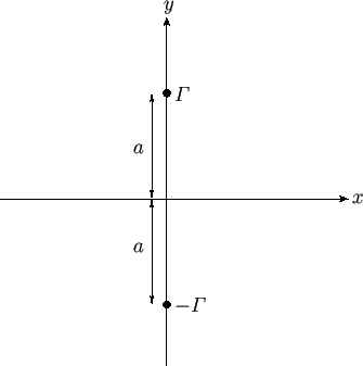 |
As a second example, consider the situation, illustrated in Figure 6.3, in which there are two
vortex filaments of intensities
 and
and
 situated at
  ,
,  .
As before, the complex velocity potential of the resulting flow pattern is the sum of the complex potentials of each filament taken in isolation.
Hence, from Section 6.4,
 |
(6.48) |
Thus, the stream function of the flow pattern is
![$\displaystyle \psi(x,y) =\frac{{\mit\Gamma}}{2\pi}\,\ln\left[\frac{x^{\,2}+(y-a)^2}{x^{\,2}+(y+a)^2}\right].$](img2034.png) |
(6.49) |
As before,
 , which implies that there is zero flow normal to the plane
  (because the plane corresponds to
a streamline). Hence, in the region
  , we could interpret the
previous stream function as that generated by a single vortex filament of intensity
 , located at the point
  ,
,  ,
in the presence of a planar rigid boundary at
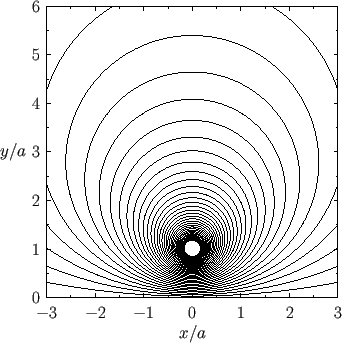
  . The streamlines
of the resulting flow pattern are shown in Figure 6.4. We conclude that a vortex filament reverses its sense of
rotation (i.e.,
 ) when ``reflected'' in a boundary plane.
Figure:
Stream lines of the two-dimensional flow pattern due to a vortex filament at  ,
,  in the presence
of a rigid boundary at
  .
.
 |
As a final example, consider the situation, illustrated in Figure 6.5, in which there is an impenetrable circular cylinder
of radius  , centered on the origin, and a line source of strength
  located at
  ,
,  , where
 . Consider the so-called analog problem, also illustrated in Figure 6.5, in which the cylinder is
replaced by a source of strength
  , located at
  ,
,  , where
  , and a source of strength
 , located at the origin. We can think of these two sources as the ``images'' of the external source in the
cylinder.
Moreover, given that the solutions of Laplace's equation are unique, if the analog problem can be adjusted in such a manner that
  is a streamline
then the flow in the region
  will become identical to that in the actual problem. The
complex velocity potential in the analog problem is simply
![$\displaystyle F(z) = -\frac{Q}{2\pi}\,\ln(z-b)-\frac{Q}{2\pi}\,\ln(z-c)+ \frac{Q}{2\pi}\,\ln z = - \frac{Q}{2\pi}\ln\left[\frac{(z-b)\,(z-c)}{z}\right].$](img2042.png) |
(6.50) |
Hence, writing
 , the corresponding stream function takes the form
![$\displaystyle \psi(r,\theta) = -\frac{Q}{2\pi}\,\tan^{-1}\left[\frac{(r-b\,c/r)\,\sin\theta}{(r+b\,c/r)\,\cos\theta-(b+c)}\right].$](img2044.png) |
(6.51) |
We require the surface of the cylinder,  , to be a streamline: that is,
 constant.
This is easily achieved by setting
 . Thus, the stream function becomes
![$\displaystyle \psi(r,\theta) = -\frac{Q}{2\pi}\,\tan^{-1}\left[\frac{(r/a-a/r)\,\sin\theta}{(r/a+a/r)\,\cos\theta-(b/a+a/b)}\right].$](img2047.png) |
(6.52) |
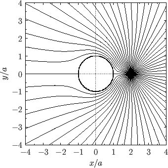
The corresponding streamlines in the region external to the cylinder are illustrated in Figure 6.6.
Figure 6.5:
A line source in the presence of an impenetrable circular cylinder.
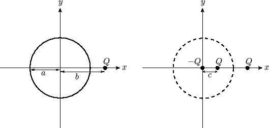 |
Figure:
Stream lines of the two-dimensional flow pattern due to a line source at  ,
,  in the presence
of a rigid circular cylinder of radius
  centered on the origin.
 |


Next: Conformal Maps
Up: Two-Dimensional Potential Flow
Previous: Complex Velocity
Richard Fitzpatrick
2016-03-31

![]() located at the points
located at the points ![]()
![]() . (See Figure 6.1.)
The complex velocity potential of the resulting flow pattern is the sum of the complex potentials of each source taken in isolation.
Hence, from Section 6.4,
. (See Figure 6.1.)
The complex velocity potential of the resulting flow pattern is the sum of the complex potentials of each source taken in isolation.
Hence, from Section 6.4,


![]() and
and
![]() situated at
situated at ![]() ,
, ![]() .
As before, the complex velocity potential of the resulting flow pattern is the sum of the complex potentials of each filament taken in isolation.
Hence, from Section 6.4,
.
As before, the complex velocity potential of the resulting flow pattern is the sum of the complex potentials of each filament taken in isolation.
Hence, from Section 6.4,
![$\displaystyle \psi(x,y) =\frac{{\mit\Gamma}}{2\pi}\,\ln\left[\frac{x^{\,2}+(y-a)^2}{x^{\,2}+(y+a)^2}\right].$](img2034.png)

![]() , centered on the origin, and a line source of strength
, centered on the origin, and a line source of strength ![]() located at
located at ![]() ,
, ![]() , where
, where
![]() . Consider the so-called analog problem, also illustrated in Figure 6.5, in which the cylinder is
replaced by a source of strength
. Consider the so-called analog problem, also illustrated in Figure 6.5, in which the cylinder is
replaced by a source of strength ![]() , located at
, located at ![]() ,
, ![]() , where
, where ![]() , and a source of strength
, and a source of strength
![]() , located at the origin. We can think of these two sources as the ``images'' of the external source in the
cylinder.
Moreover, given that the solutions of Laplace's equation are unique, if the analog problem can be adjusted in such a manner that
, located at the origin. We can think of these two sources as the ``images'' of the external source in the
cylinder.
Moreover, given that the solutions of Laplace's equation are unique, if the analog problem can be adjusted in such a manner that ![]() is a streamline
then the flow in the region
is a streamline
then the flow in the region ![]() will become identical to that in the actual problem. The
complex velocity potential in the analog problem is simply
will become identical to that in the actual problem. The
complex velocity potential in the analog problem is simply
![$\displaystyle F(z) = -\frac{Q}{2\pi}\,\ln(z-b)-\frac{Q}{2\pi}\,\ln(z-c)+ \frac{Q}{2\pi}\,\ln z = - \frac{Q}{2\pi}\ln\left[\frac{(z-b)\,(z-c)}{z}\right].$](img2042.png)
![$\displaystyle \psi(r,\theta) = -\frac{Q}{2\pi}\,\tan^{-1}\left[\frac{(r-b\,c/r)\,\sin\theta}{(r+b\,c/r)\,\cos\theta-(b+c)}\right].$](img2044.png)
![$\displaystyle \psi(r,\theta) = -\frac{Q}{2\pi}\,\tan^{-1}\left[\frac{(r/a-a/r)\,\sin\theta}{(r/a+a/r)\,\cos\theta-(b/a+a/b)}\right].$](img2047.png)
