


Next: Energy Stored in an
Up: Inductance
Previous: Mutual Inductance
Self Inductance
We do not necessarily need two circuits in order to have inductive effects. Consider
a single conducting circuit around which a current  is
flowing. This current generates a magnetic field
is
flowing. This current generates a magnetic field  which
gives rise to a magnetic flux
which
gives rise to a magnetic flux  linking the
circuit. We expect the flux to be directly proportional
to the current , given the linear nature of the laws of magnetostatics,
and the definition of magnetic flux. Thus, we can write
linking the
circuit. We expect the flux to be directly proportional
to the current , given the linear nature of the laws of magnetostatics,
and the definition of magnetic flux. Thus, we can write
 |
(241) |
where the constant of proportionality  is called the self inductance of the
circuit. Like mutual inductance, the self inductance
of a circuit is measured in units of henries, and is a
purely geometric quantity, depending only on the
shape of the circuit and number of turns in the circuit.
is called the self inductance of the
circuit. Like mutual inductance, the self inductance
of a circuit is measured in units of henries, and is a
purely geometric quantity, depending only on the
shape of the circuit and number of turns in the circuit.
If the current flowing around the circuit changes by an
amount  in a time interval
  then the
magnetic flux linking the circuit changes by an amount
then the
magnetic flux linking the circuit changes by an amount
 in the same time interval. According to
Faraday's law, an emf
in the same time interval. According to
Faraday's law, an emf
 |
(242) |
is generated around the circuit. Since
,
this emf can also be written
 |
(243) |
Thus, the emf generated around the circuit due to its own current is directly
proportional to the rate at which the current changes. Lenz's law, and
common sense, demand that if the current is increasing then the emf should
always
act to reduce the current, and vice versa. This is easily appreciated,
since if
the emf acted to increase the
current when the current was increasing then we would clearly get an unphysical
positive feedback
effect in which the current continued to increase without limit. It follows, from
Eq. (243), that the
self inductance of a circuit is necessarily a positive number. This
is not the case for mutual inductances, which can be either positive or negative.
Consider a solenoid of length  and cross-sectional
area
and cross-sectional
area  . Suppose that the solenoid has
  turns.
When a current flows in the solenoid, a uniform axial field of magnitude
turns.
When a current flows in the solenoid, a uniform axial field of magnitude
 |
(244) |
is generated in the core of the solenoid. The field-strength outside the core
is
negligible. The magnetic flux linking a single turn of the solenoid is
 . Thus, the magnetic flux linking all turns of
the solenoid is
. Thus, the magnetic flux linking all turns of
the solenoid is
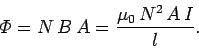 |
(245) |
According to Eq. (241), the self inductance of the solenoid is given by
 , which reduces to
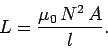 |
(246) |
Note that is positive. Furthermore, is a geometric quantity depending
only on the dimensions of the solenoid, and the number of turns in the solenoid.
Engineers
like to reduce all pieces of electrical apparatus, no matter how complicated, to
an equivalent circuit consisting of a network of
just four different types
of component. These four basic components are emfs, resistors, capacitors,
and inductors. An inductor is simply a pure self inductance, and is usually
represented a little solenoid in circuit diagrams. In practice, inductors
generally consist of short air-cored solenoids wound from enameled copper wire.
Next: Energy Stored in an
Up: Inductance
Previous: Mutual Inductance
Richard Fitzpatrick
2007-07-14