Two-Dimensional Fourier Optics
Consider a monochromatic plane light wave, propagating in the  -direction, which is normally incident on an opaque
screen that occupies the plane
-direction, which is normally incident on an opaque
screen that occupies the plane  . Suppose that there is an irregularly shaped aperture cut in the screen, and
that the light that passes through this aperture travels to a flat projection screen occupying the plane
. Suppose that there is an irregularly shaped aperture cut in the screen, and
that the light that passes through this aperture travels to a flat projection screen occupying the plane  .
We wish to determine the interference/diffraction pattern that appears on the projection screen, as a function of the size
and shape of the aperture. We can achieve this goal by employing a modified
version of Huygen's principle. In Section 10.6, we
divided the aperture into infinitesimal parallel strips of equal height, and argued that each
strip emits a cylindrical wave in the forward direction that has the same amplitude and phase as the
light that illuminates it from behind. For the case of an irregularly shaped aperture, we can similarly divide the aperture into
infinitesimal squares of equal area, and argue that each square emits a spherical wave in the forward direction that has the
same amplitude and phase as the light that illuminates it from behind. [Recall that line sources and point sources emit
cylindrical and spherical waves, respectively. (See Sections 7.4 and 7.5.)]
Using analogous arguments to those employed in Section 10.2, we can show that
provided
.
We wish to determine the interference/diffraction pattern that appears on the projection screen, as a function of the size
and shape of the aperture. We can achieve this goal by employing a modified
version of Huygen's principle. In Section 10.6, we
divided the aperture into infinitesimal parallel strips of equal height, and argued that each
strip emits a cylindrical wave in the forward direction that has the same amplitude and phase as the
light that illuminates it from behind. For the case of an irregularly shaped aperture, we can similarly divide the aperture into
infinitesimal squares of equal area, and argue that each square emits a spherical wave in the forward direction that has the
same amplitude and phase as the light that illuminates it from behind. [Recall that line sources and point sources emit
cylindrical and spherical waves, respectively. (See Sections 7.4 and 7.5.)]
Using analogous arguments to those employed in Section 10.2, we can show that
provided
 |
(10.70) |
where  is the characteristic size of the aperture, and
  is the wavelength of the light that illuminates it from behind, we are
in the far-field limit. In this limit, the interference/diffraction pattern appearing on the projection screen is entirely due to the phase
differences between the spherical waves that travel to a given point on the screen from different parts of the aperture. These
phase differences are produced by the slightly different distances traveled by these waves.
is the wavelength of the light that illuminates it from behind, we are
in the far-field limit. In this limit, the interference/diffraction pattern appearing on the projection screen is entirely due to the phase
differences between the spherical waves that travel to a given point on the screen from different parts of the aperture. These
phase differences are produced by the slightly different distances traveled by these waves.
Consider a spherical wave emitted from the point  ,
,  ,
,  in the aperture that travels to the point
 ,
,  ,
,  on the projection screen. The distance traveled by this wave is
where
 and
and
 are the angular coordinates of the point on the projection screen. Here, we are assuming that
 |
(10.72) |
The wavefunction at the point  ,
,  on the projection screen is a linear superposition of the spherical waves that travel to it from all
parts of the aperture. It follows that
on the projection screen is a linear superposition of the spherical waves that travel to it from all
parts of the aperture. It follows that
 |
(10.73) |
Here, 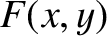 is an aperture function that takes the value
  in the unblocked parts of the opaque screen, where
  is the aperture area, and the
value zero in the blocked parts. We have neglected the
is the aperture area, and the
value zero in the blocked parts. We have neglected the  variation of the wave amplitudes (see Section 7.5)
because we are working in the far-field limit. It follows, from Equations (10.71) and (10.73), that
Here, we have made use of the fact that
variation of the wave amplitudes (see Section 7.5)
because we are working in the far-field limit. It follows, from Equations (10.71) and (10.73), that
Here, we have made use of the fact that
 ,
,
 , and have also assumed that the aperture function is an even function of
both
, and have also assumed that the aperture function is an even function of
both  and (i.e., the aperture is symmetric about
  and
and  ). The intensity of the light at the point , on the
projection screen is thus
). The intensity of the light at the point , on the
projection screen is thus
![$\displaystyle {\cal I}(\theta_x,\theta_y)\propto \langle \psi^{\,2}(\theta_x,\t...
...infty}^\infty F(x,y)\,\cos(k\,\theta_x\,x+k\,\theta_y\,y)\,dx\,dy\right]^{\,2}.$](img3509.png) |
(10.75) |
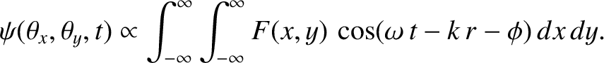
Figure:
Far-field interference/diffraction pattern produced by a rectangular aperture for which  . Dark regions indicate
high light intensity.
. Dark regions indicate
high light intensity.
|
|
Consider a rectangular aperture that occupies the region
 and
and
 in the - plane.
The intensity of the interference/diffraction pattern on the projection screen produced by such an aperture is
in the - plane.
The intensity of the interference/diffraction pattern on the projection screen produced by such an aperture is
![$\displaystyle {\cal I}(\theta_x,\theta_y)\propto \left[\int_{-b/2}^{b/2}\int_{-...
...2}\cos(k\,\theta_x\,x+k\,\theta_y\,y)\,\frac{dx}{a}\,\frac{dy}{b}\right]^{\,2},$](img3514.png) |
(10.76) |
which yields
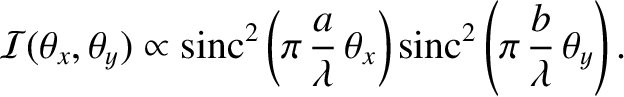 |
(10.77) |
This pattern is shown in Figure 10.13. It consists of a strong central maximum, that extends over the region
 and
and
 , surrounded by much weaker secondary maxima arranged on a rectangular grid. Incidentally, our assumption that
,
is only
self-consistent provided
, surrounded by much weaker secondary maxima arranged on a rectangular grid. Incidentally, our assumption that
,
is only
self-consistent provided
 ,
,  (i.e., provided the wavelength of the light is much less than the dimensions of
the aperture).
(i.e., provided the wavelength of the light is much less than the dimensions of
the aperture).
Figure:
The function
 .
.
|
|
Consider a circular aperture that occupies the region
 in the - plane. Let
 ,
,
 ,
,
 , and
, and
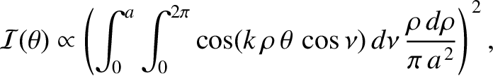
 . The
intensity of the interference/diffraction pattern on the projection screen produced by such an aperture is
. The
intensity of the interference/diffraction pattern on the projection screen produced by such an aperture is
![$\displaystyle {\cal I}(\theta,\phi') \propto\left(\int_0^a\int_0^{2\pi}\cos[k\,...
...theta\,\cos(\phi-\phi')]\,\frac{\rho\,d\phi\,d\rho}{\pi\,a^{\,2}}\right)^{\,2},$](img3526.png) |
(10.78) |
or
 |
(10.79) |
where
 .
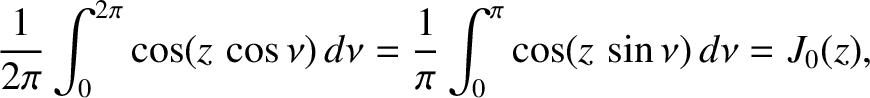
It is readily demonstrated that (Abramowitz and Stegun 1965)
.
It is readily demonstrated that (Abramowitz and Stegun 1965)
 |
(10.80) |
where  is the Bessel function of degree zero introduced in Section 7.6.
It follows that
is the Bessel function of degree zero introduced in Section 7.6.
It follows that
![$\displaystyle {\cal I}(\theta) \propto \left[\frac{2}{\pi\,a^{\,2}}\int_0^a J_0...
...ft[\frac{2}{(k\,\theta\,a)^2}\int_0^{k\theta\,a}
J_0(z')\,z'\,dz'\right]^{\,2}.$](img3530.png) |
(10.81) |
It can be shown that (Gradshteyn and Ryzhik 1980)
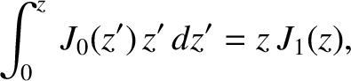 |
(10.82) |
where (Abramowitz and Stegun 1965)
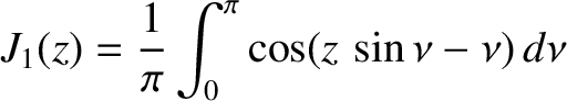 |
(10.83) |
is a Bessel function of degree one. Hence,
![$\displaystyle {\cal I}(\theta)\propto \left[\frac{2\,J_1(k\,a\,\theta)}{k\,a\,\theta}\right]^{\,2}.$](img3533.png) |
(10.84) |
Figure 10.14 shows the function
, whereas Table 10.1 lists the first few values
of at which this function is zero. Finally, Figure 10.15 shows the interference/diffraction pattern
associated with a circular aperture. The pattern consists of a central disk, known as an Airy disk,
surrounded by much fainter concentric rings. The angular radius of the Airy disk is
 where
where
 is the first zero of the function
. It follows that
is the first zero of the function
. It follows that
 |
(10.85) |
where  is the diameter of the aperture.
Table: 10.1
First few zeros of the function
. Source: Abramowitz and Stegun 1965.
 |
 |
|
|
| |
|
|
|
| 1 |
3.83171 |
6 |
19.61586 |
| 2 |
7.01559 |
7 |
22.76008 |
| 3 |
10.17347 |
8 |
25.90367 |
| 4 |
13.32369 |
9 |
29.04683 |
| 5 |
16.47063 |
10 |
32.18968 |
|
Figure 10.15:
Far-field interference/diffraction pattern produced by a circular aperture of radius  . Dark regions indicate high light intensity.
|
|
As we have already mentioned (see Section 10.7), when a point light source, such as a star, is observed in a telescope, what
is actually seen is the diffraction patten of the source produced by the objective aperture. If the aperture is
circular then then the telescope images the star as an Airy disk, surrounded by much fainter rings. Likewise, the
telescope images two neighboring stars as two Airy disks. The Rayleigh criterion (see Section 10.7) for resolving the two stars (i.e.,
for being able to tell that there are two stars, rather than one)
is that the angular distance,
 , between the stars be greater than the angular radii of their Airy disks. This yields
 |
(10.86) |
where  is the diameter of the telescope's objective aperture. Thus, the minimum angular resolution of the
telescope is
is the diameter of the telescope's objective aperture. Thus, the minimum angular resolution of the
telescope is
 |
(10.87) |
which is a slightly more accurate version of the criterion given in Section 10.7.
![\includegraphics[width=0.8\textwidth]{Chapter10/fig10_13.eps}](img3510.png)
![\includegraphics[width=0.8\textwidth]{Chapter10/fig10_15.eps}](img3538.png)
![$\displaystyle r = \left[(x-x')^2+(y-y')^2+R^{\,2}\right]^{1/2}=R\left[1+\frac{1...
...R}-\theta_y\,\frac{y}{R} + {\cal O}\left(\frac{d^{\,2}}{R^{\,2}}\right)\right],$](img3492.png)
![$\displaystyle \int_{-\infty}^\infty\int_{-\infty}^\infty F(x,y)\,\cos\left[\ome...
...,2}/2+\theta_y^{\,2}/2\right)-\phi + k\,\theta_x\,x+k\,\theta_y\,y\right]dx\,dy$](img3502.png)


![\includegraphics[width=0.9\textwidth]{Chapter10/fig10_14.eps}](img3519.png)