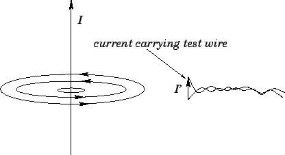
Ampère's next series of experiments involved bringing a short test wire, carrying
a current ![]() ,
close to the original wire, and investigating the force exerted on the test wire
(see Fig. 29).
This experiment is not quite as clear cut as Coulomb's experiment because, unlike
electric charges,
electric currents cannot exist as point entities--they
have to flow in complete circuits. We must
imagine that the circuit which connects with the central wire is sufficiently
far away that it has no appreciable influence on the outcome of the experiment.
The circuit which connects with
the test wire is more problematic. Fortunately, if the
feed wires are twisted around each other, as indicated in Fig. 29, then
they effectively cancel one another out, and also do not influence the outcome of
the experiment.
,
close to the original wire, and investigating the force exerted on the test wire
(see Fig. 29).
This experiment is not quite as clear cut as Coulomb's experiment because, unlike
electric charges,
electric currents cannot exist as point entities--they
have to flow in complete circuits. We must
imagine that the circuit which connects with the central wire is sufficiently
far away that it has no appreciable influence on the outcome of the experiment.
The circuit which connects with
the test wire is more problematic. Fortunately, if the
feed wires are twisted around each other, as indicated in Fig. 29, then
they effectively cancel one another out, and also do not influence the outcome of
the experiment.
Ampère discovered that the force exerted on the test wire is directly proportional
to its length. He also made the following observations.
If the current in the test wire
(i.e., the test current) flows parallel to the current in the central wire
then the two wires attract one another. If the current in the test
wire is reversed then the two wires repel one another.
If the test current points radially towards the central wire
(and the current in the central wire flows upwards) then the test wire
is subject to a downwards force. If the test current is reversed then the force is
upwards. If the test current is rotated in a single plane, so that it starts
parallel to the central current and ends up pointing radially
towards it, then the force on
the test wire is of constant magnitude, and is always at right-angles to the
test current. If the test current is parallel to a magnetic loop then there is
no force exerted on the test wire. If the test current is rotated in
a single plane, so that it starts parallel to the central current and ends up
pointing along a magnetic loop, then the magnitude of the force on the
test wire attenuates like ![]() (where
(where ![]() is the angle the current
is turned through--
is the angle the current
is turned through--![]() corresponds to the
case where the test current is parallel to the central current),
and its direction is again always at right-angles to
the test current. Finally, Ampère was able to establish that the attractive
force between two parallel current carrying wires is proportional to the product of
the two currents, and
falls off like the inverse of the perpendicular
distance between the wires.
corresponds to the
case where the test current is parallel to the central current),
and its direction is again always at right-angles to
the test current. Finally, Ampère was able to establish that the attractive
force between two parallel current carrying wires is proportional to the product of
the two currents, and
falls off like the inverse of the perpendicular
distance between the wires.
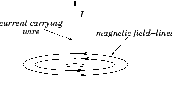
This rather complicated force law can be summed up succinctly in vector notation
provided that we define a vector field ![]() , called the magnetic field,
whose direction is always parallel to the loops mapped out by a small
compass. The dependence of the force per unit length,
, called the magnetic field,
whose direction is always parallel to the loops mapped out by a small
compass. The dependence of the force per unit length, ![]() , acting on a
test wire with the different
possible orientations of the test current is described by
, acting on a
test wire with the different
possible orientations of the test current is described by
| (230) |
| (231) |
The concept of a magnetic field allows the calculation of the force on a test wire to be conveniently split into two parts. In the first part, we calculate the magnetic field generated by the current flowing in the central wire. This field circulates in the plane normal to the wire: its magnitude is proportional to the central current, and inversely proportional to the perpendicular distance from the wire. In the second part, we use Eq. (229) to calculate the force per unit length acting on a short current carrying wire located in the magnetic field generated by the central current. This force is perpendicular to both the magnetic field and the direction of the test current. Note that, at this stage, we have no reason to suppose that the magnetic field has any real physical existence. It is introduced merely to facilitate the calculation of the force exerted on the test wire by the central wire.