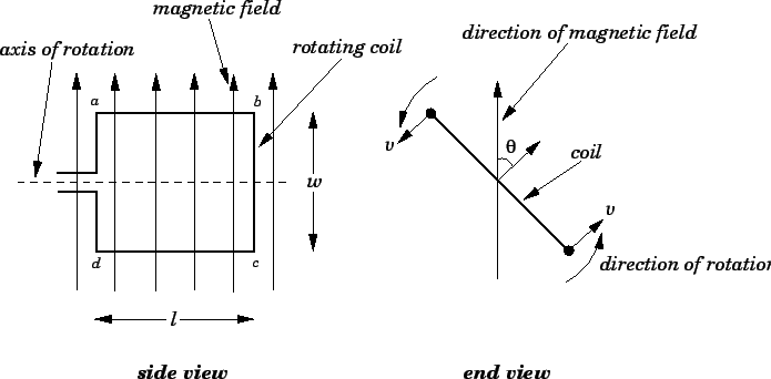
Let ![]() be the length of the coil along its axis of rotation, and
be the length of the coil along its axis of rotation, and ![]() the
width of the coil perpendicular to this axis. Suppose that the
coil rotates with constant angular velocity
the
width of the coil perpendicular to this axis. Suppose that the
coil rotates with constant angular velocity ![]() in a uniform
magnetic field of strength
in a uniform
magnetic field of strength ![]() . The velocity
. The velocity ![]() with which the the two
long sides of the coil (i.e.,
sides
with which the the two
long sides of the coil (i.e.,
sides ![]() and
and ![]() ) move through the magnetic field is simply the product
of the angular velocity of rotation
) move through the magnetic field is simply the product
of the angular velocity of rotation ![]() and the distance
and the distance ![]() of each
side from the axis of rotation, so
of each
side from the axis of rotation, so
![]() . The motional emf
induced in each side is given by
. The motional emf
induced in each side is given by
![]() , where
, where ![]() is
the component of the magnetic field perpendicular to instantaneous direction
of motion of the side in question.
If the direction of the magnetic field subtends an
angle
is
the component of the magnetic field perpendicular to instantaneous direction
of motion of the side in question.
If the direction of the magnetic field subtends an
angle ![]() with the normal direction to
the coil, as shown in the figure, then
with the normal direction to
the coil, as shown in the figure, then
![]() .
Thus, the magnitude of the motional emf generated in sides
.
Thus, the magnitude of the motional emf generated in sides ![]() and
and ![]() is
is
| (209) |
Suppose that the direction of rotation of the coil is such that side
![]() is moving into the page in Fig. 38 (side view), whereas side
is moving into the page in Fig. 38 (side view), whereas side
![]() is moving out of the page. The motional emf induced in side
is moving out of the page. The motional emf induced in side ![]() acts from
acts from
![]() to
to ![]() . Likewise, the motional
emf induce in side
. Likewise, the motional
emf induce in side ![]() acts from
acts from ![]() to
to ![]() . It can be seen that both emfs
act in the clockwise direction around the coil. Thus, the net emf
. It can be seen that both emfs
act in the clockwise direction around the coil. Thus, the net emf
![]() acting around the
coil is
acting around the
coil is
![]() . If the coil has
. If the coil has ![]() turns then the net emf becomes
turns then the net emf becomes
![]() . Thus, the general expression for the emf generated around a
steadily rotating, multi-turn coil in a uniform magnetic field is
. Thus, the general expression for the emf generated around a
steadily rotating, multi-turn coil in a uniform magnetic field is
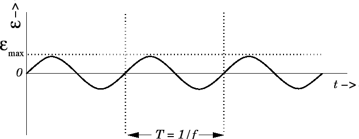
Figure 39 shows the emf specified in Eq. (211) plotted as a function
of time. It can be seen that the variation of the emf with time is
sinusoidal in nature. The emf attains its peak values when the plane of
the coil is parallel to the plane of the magnetic field, passes through
zero when the plane of the coil is perpendicular to the magnetic field, and reverses
sign every half period of revolution of the coil. The emf is periodic
(i.e., it continually repeats the same pattern in time), with
period ![]() (which is, of course, the rotation period of the coil).
(which is, of course, the rotation period of the coil).
Suppose that some load (e.g., a light-bulb, or an electric heating
element) of resistance ![]() is connected across the terminals of the
generator. In practice, this is achieved by connecting the two ends of the
coil to rotating rings which are then connected to the external circuit by means
of metal brushes. According to Ohm's law, the current
is connected across the terminals of the
generator. In practice, this is achieved by connecting the two ends of the
coil to rotating rings which are then connected to the external circuit by means
of metal brushes. According to Ohm's law, the current ![]() which flows in the
load is given by
which flows in the
load is given by
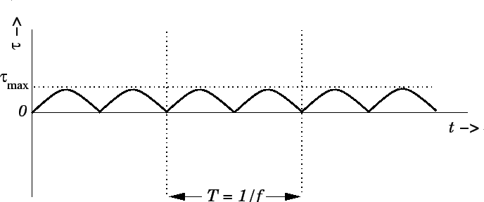
The current ![]() which flows through the load must also flow around the coil.
Since the coil is situated in a magnetic field, this current gives rise to
a torque on the coil which, as is easily demonstrated, acts to slow down its
rotation. According to Sect. 8.11, the braking torque
which flows through the load must also flow around the coil.
Since the coil is situated in a magnetic field, this current gives rise to
a torque on the coil which, as is easily demonstrated, acts to slow down its
rotation. According to Sect. 8.11, the braking torque ![]() acting
on the coil is given by
acting
on the coil is given by
| (214) |
| (216) |
Equations (210), (213), and (215) yield
Virtually all commercial power stations generate electricity using AC generators.
The external power needed to turn the generating coil is usually supplied by
a steam turbine (steam blasting against fan-like blades which are
forced into rotation). Water is vaporized to produce
high pressure
steam by burning coal, or by using the energy released inside a nuclear
reactor.
Of course, in hydroelectric power stations, the power needed
to turn the generator coil is supplied by a water turbine (which is similar
to a steam turbine, except that falling water plays the role of the steam).
Recently, a new type of power station has been developed in which the
power needed to rotate the generating coil is supplied by a gas turbine
(basically, a large jet engine which burns natural gas). In the United States
and Canada, the alternating emf generated by power stations oscillates at
![]() Hz, which means that the
generator coils in power stations rotate exactly
sixty times a second. In Europe, and much of the rest of the world, the oscillation frequency
of commercially generated electricity is
Hz, which means that the
generator coils in power stations rotate exactly
sixty times a second. In Europe, and much of the rest of the world, the oscillation frequency
of commercially generated electricity is ![]() Hz.
Hz.