Broadly speaking, only electric currents can be measured directly. Potential differences and resistances are usually inferred from measurements of electric currents. The most accurate method of measuring an electric current is by using a device called a galvanometer.
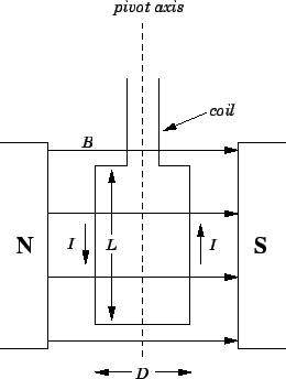
A galvanometer consists of a rectangular conducting coil which is free to pivot vertically
in an approximately uniform horizontal
magnetic field ![]() --see Fig. 31. The magnetic field is usually generated
by a permanent magnet. Suppose that a current
--see Fig. 31. The magnetic field is usually generated
by a permanent magnet. Suppose that a current ![]() runs through the coil.
What are the forces exerted on the coil by the magnetic field?
According to Eq. (152), the
forces exerted on those sections of the coil in which the
current runs in the horizontal plane are directed vertically up or down.
These forces are irrelevant, since they are absorbed by the support structure of
the coil, which does not allow the coil to move vertically.
Equation (152) also implies that the force exerted on
the section of the coil in which the current flows downward is of magnitude
runs through the coil.
What are the forces exerted on the coil by the magnetic field?
According to Eq. (152), the
forces exerted on those sections of the coil in which the
current runs in the horizontal plane are directed vertically up or down.
These forces are irrelevant, since they are absorbed by the support structure of
the coil, which does not allow the coil to move vertically.
Equation (152) also implies that the force exerted on
the section of the coil in which the current flows downward is of magnitude
![]() , where
, where ![]() the length of this section, and is directed out of
the page (in the figure). Likewise, the force exerted on
the section of the coil in which the current flows upward is also of
magnitude
the length of this section, and is directed out of
the page (in the figure). Likewise, the force exerted on
the section of the coil in which the current flows upward is also of
magnitude ![]() , and is directed into the page. These two forces
exert a torque on the coil which tries to twist it about its vertical
axis in an anti-clockwise direction (looking from above). Using the
usual definition of torque (i.e., torque is the product of
the force and the perpendicular distance from the line of action of
the force to the axis of rotation), the net torque
, and is directed into the page. These two forces
exert a torque on the coil which tries to twist it about its vertical
axis in an anti-clockwise direction (looking from above). Using the
usual definition of torque (i.e., torque is the product of
the force and the perpendicular distance from the line of action of
the force to the axis of rotation), the net torque ![]() acting on the coil is
acting on the coil is
| (183) |
The coil in a galvanometer is usually suspended from a torsion wire. The
wire exerts a restoring torque on the coil which tries to twist it back to
its original position. The strength of this restoring torque is directly
proportional to the angle of twist
![]() . It follows that,
in equilibrium, where the magnetic torque balances the restoring torque,
the angle of twist
. It follows that,
in equilibrium, where the magnetic torque balances the restoring torque,
the angle of twist
![]() is directly proportional
to the current
is directly proportional
to the current ![]() flowing around the coil. The angle of twist can be measured by
attaching a pointer to the coil, or, even better, by mounting a mirror on the coil,
and reflecting a light beam off the mirror. Since
flowing around the coil. The angle of twist can be measured by
attaching a pointer to the coil, or, even better, by mounting a mirror on the coil,
and reflecting a light beam off the mirror. Since
![]() , the
device can easily be calibrated by running a known current through it.
, the
device can easily be calibrated by running a known current through it.
There is, of course, a practical limit to how large the angle of twist
![]() can become in a galvanometer. If the torsion wire is twisted through
too great an angle
then it will deform permanently, and will eventually snap.
In order to prevent this from happening, most galvanometers are equipped
with a ``stop'' which physically prevents the coil from twisting through more than
(say)
can become in a galvanometer. If the torsion wire is twisted through
too great an angle
then it will deform permanently, and will eventually snap.
In order to prevent this from happening, most galvanometers are equipped
with a ``stop'' which physically prevents the coil from twisting through more than
(say) ![]() . Thus, there is a maximum current
. Thus, there is a maximum current ![]() which
a galvanometer can measure. This is usually referred to as the
full-scale-deflection current. The full-scale-deflection current in
conventional galvanometers is usually pretty small: e.g.,
which
a galvanometer can measure. This is usually referred to as the
full-scale-deflection current. The full-scale-deflection current in
conventional galvanometers is usually pretty small: e.g.,
![]() .
So, what do we do if we want to measure a large current?
.
So, what do we do if we want to measure a large current?
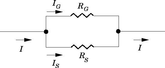
What we do is to connect a shunt resistor in parallel with the
galvanometer, so that most of the current flows through the resistor, and
only a small fraction of the current flows through the galvanometer itself. This is
illustrated in Fig. 32. Let the resistance of the galvanometer
be ![]() , and the resistance of the shunt resistor be
, and the resistance of the shunt resistor be ![]() . Suppose that
we want to be able to measure the total current
. Suppose that
we want to be able to measure the total current ![]() flowing through the galvanometer
and the shunt resistor up to a maximum value of
flowing through the galvanometer
and the shunt resistor up to a maximum value of ![]() .
We can achieve this if the current
.
We can achieve this if the current ![]() flowing through the galvanometer equals the
full-scale-deflection current
flowing through the galvanometer equals the
full-scale-deflection current ![]() when
when ![]() . In this
case, the current
. In this
case, the current ![]() flowing through the shunt resistor takes the
value
flowing through the shunt resistor takes the
value
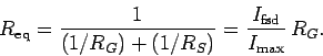
![]() . The potential drop across the shunt resistor is
therefore
. The potential drop across the shunt resistor is
therefore
![]() . This potential drop must match the
potential drop
. This potential drop must match the
potential drop
![]() across the galvanometer, since the galvanometer is
connected in parallel with the shunt resistor. It follows that
across the galvanometer, since the galvanometer is
connected in parallel with the shunt resistor. It follows that
| (184) |
| (185) |
| (186) |
 |
(187) |
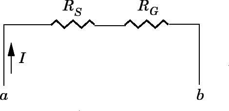
A galvanometer can be used to measure potential difference as well as current (although, in the former case, it is really measuring current). In order to measure the potential difference
| (188) |
| (189) |
| (190) |