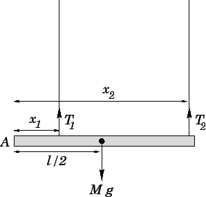
Let us first locate the centre of mass of the rod, which is situated at the rod's mid-point,
a distance ![]() from reference point
from reference point ![]() (see Fig. 91). There are
three forces acting on the rod: the gravitational force,
(see Fig. 91). There are
three forces acting on the rod: the gravitational force, ![]() , and the two tension forces,
, and the two tension forces,
![]() and
and ![]() . Each of these forces is directed vertically. Thus, the condition that zero net force
acts on the system reduces to the condition that the net vertical force is zero, which yields
. Each of these forces is directed vertically. Thus, the condition that zero net force
acts on the system reduces to the condition that the net vertical force is zero, which yields
| (470) |
Consider the torques exerted by the three above-mentioned forces about point ![]() . Each of these
torques attempts to twist the rod about an axis perpendicular to the plane of the diagram.
Hence, the condition that zero net torque acts on the system reduces to the condition that
the net torque at point
. Each of these
torques attempts to twist the rod about an axis perpendicular to the plane of the diagram.
Hence, the condition that zero net torque acts on the system reduces to the condition that
the net torque at point ![]() , about an axis perpendicular to the plane of the diagram, is zero. The contribution
of each force to this torque is simply the product of the magnitude of the force and the
length of the associated lever arm. In each case, the length of the lever arm is equivalent to
the distance of the point of action of the force from
, about an axis perpendicular to the plane of the diagram, is zero. The contribution
of each force to this torque is simply the product of the magnitude of the force and the
length of the associated lever arm. In each case, the length of the lever arm is equivalent to
the distance of the point of action of the force from ![]() , measured along the length of the rod.
Hence, setting the net torque to zero, we obtain
, measured along the length of the rod.
Hence, setting the net torque to zero, we obtain
| (471) |
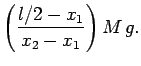
The previous two equations can be solved to give
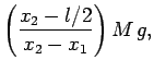 |
(472) | ||
 |
(473) |
| (474) | |||
| (475) |
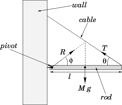
Consider a uniform rod of mass ![]() and length
and length ![]() which is free to rotate in the vertical
plane about a fixed pivot attached to one of its ends. The other end of the rod is
attached to a fixed cable. We can imagine that both the pivot and the cable are anchored
in the same vertical wall. See Fig. 92.
Suppose that the rod is level, and that the cable subtends an angle
which is free to rotate in the vertical
plane about a fixed pivot attached to one of its ends. The other end of the rod is
attached to a fixed cable. We can imagine that both the pivot and the cable are anchored
in the same vertical wall. See Fig. 92.
Suppose that the rod is level, and that the cable subtends an angle ![]() with the horizontal.
Assuming that the rod is in equilibrium, what is the magnitude
of the tension,
with the horizontal.
Assuming that the rod is in equilibrium, what is the magnitude
of the tension, ![]() , in the cable, and what is the direction and magnitude of the
reaction,
, in the cable, and what is the direction and magnitude of the
reaction, ![]() , at the pivot?
, at the pivot?
As usual, the centre of mass of the rod lies at its mid-point.
There are three forces acting on the rod: the reaction, ![]() ; the weight,
; the weight, ![]() ; and the tension,
; and the tension,
![]() . The reaction acts at the pivot. Let
. The reaction acts at the pivot. Let ![]() be
the angle subtended by the reaction with the horizontal, as shown in Fig. 92.
The weight acts at the centre of mass of the rod, and is directed
vertically downwards. Finally, the tension acts at the end of the rod, and is directed along
the cable.
be
the angle subtended by the reaction with the horizontal, as shown in Fig. 92.
The weight acts at the centre of mass of the rod, and is directed
vertically downwards. Finally, the tension acts at the end of the rod, and is directed along
the cable.
Resolving horizontally, and setting the net horizontal force acting on the rod to zero,
we obtain
Let us evaluate the net torque acting
at the pivot point (about an axis perpendicular to the plane of the diagram).
The reaction, ![]() , does not contribute to this torque, since it acts at the pivot point.
The length of the lever arm associated with the weight,
, does not contribute to this torque, since it acts at the pivot point.
The length of the lever arm associated with the weight, ![]() ,
is
,
is ![]() .
Simple trigonometry reveals that the length of the lever
arm associated with the tension,
.
Simple trigonometry reveals that the length of the lever
arm associated with the tension, ![]() , is
, is ![]() . Hence, setting the net
torque about the pivot point to zero, we obtain
. Hence, setting the net
torque about the pivot point to zero, we obtain
Equations (476) and (477) can be solved to give
| (481) |
| (482) |
One important point to note about the above solution is that if ![]() then the lines of action of the three forces--
then the lines of action of the three forces--![]() ,
, ![]() , and
, and ![]() --intersect at
the same point, as shown in Fig. 92. This is an illustration of a general
rule. Namely, whenever a rigid body is in equilibrium under the action of three
forces, then these forces are either mutually parallel, as shown in Fig. 91,
or their lines of action pass through the same point, as shown in Fig. 92.
--intersect at
the same point, as shown in Fig. 92. This is an illustration of a general
rule. Namely, whenever a rigid body is in equilibrium under the action of three
forces, then these forces are either mutually parallel, as shown in Fig. 91,
or their lines of action pass through the same point, as shown in Fig. 92.