Next: Van Allen Radiation Belts Up: Charged Particle Motion Previous: Adiabatic Invariants Contents
 , where
 is the electrostatic potential.
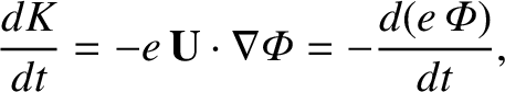
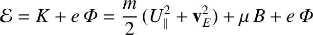
Equation (2.64) yields
is the electrostatic potential.
Equation (2.64) yields
 |
(2.83) |
 . Thus, we obtain
 |
(2.84) |
 and
and  are constants of the motion, we can rearrange
Equation (2.85) to give
are constants of the motion, we can rearrange
Equation (2.85) to give
![$\displaystyle U_\parallel = \pm \left[(2/m)\,({\cal E} -\mu\,B-e\,{\mit\Phi})-{\bf v}_E^{2}\right]^{1/2}.$](img415.png) |
(2.86) |
 .
However, particles are excluded from regions where
.
However, particles are excluded from regions where
 (because they cannot have
imaginary parallel velocities). Evidently, charged particles must reverse direction
at those points on magnetic field-lines where
(because they cannot have
imaginary parallel velocities). Evidently, charged particles must reverse direction
at those points on magnetic field-lines where
 .
Such points are termed bounce points or mirror points.
.
Such points are termed bounce points or mirror points.
Let us now consider how we might construct a device to confine a
collisionless (in other words, very high temperature) plasma. Obviously, we cannot use conventional
solid walls, because they would melt. However, it is possible to confine a
hot plasma using a magnetic field (fortunately, magnetic field-lines cannot melt). This
technique is
called magnetic confinement.
The electric field in confined plasmas is
usually weak (that is,  ), so that the
 drift
is similar in magnitude to the magnetic and curvature drifts. In this
case, the bounce point condition,
drift
is similar in magnitude to the magnetic and curvature drifts. In this
case, the bounce point condition,
 , reduces to
 be a coordinate that measures distance along the
axis of symmetry. Suppose that
be a coordinate that measures distance along the
axis of symmetry. Suppose that  corresponds to the midplane of the device
(that is, halfway between the two field-coils).
corresponds to the midplane of the device
(that is, halfway between the two field-coils).
It is clear, from the figure, that the magnetic field-strength  on a magnetic field-line situated close to the axis of the device attains a
local minimum
on a magnetic field-line situated close to the axis of the device attains a
local minimum
 at , increases symmetrically
as
at , increases symmetrically
as  increases until
reaching a maximum value
increases until
reaching a maximum value
 at about the locations of the two
field-coils, and then decreases as is further increased. According to
Equation (2.87), any particle that satisfies the inequality
at about the locations of the two
field-coils, and then decreases as is further increased. According to
Equation (2.87), any particle that satisfies the inequality
)
mirror points. The magnetic field-strength at the mirror points is
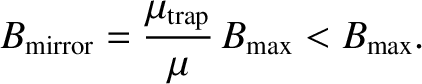 |
(2.89) |
On the midplane,
 and
and
 .
(From now on, for ease of notation, we shall write
.
(From now on, for ease of notation, we shall write
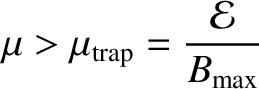
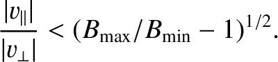
 .) Thus, the trapping
condition, Equation (2.88), reduces to
.) Thus, the trapping
condition, Equation (2.88), reduces to
![\includegraphics[height=2.5in]{Chapter02/fig2_2.eps}](img433.png) |
If plasma is placed inside a magnetic mirror machine then all of the particles whose velocities lie in the loss cone promptly escape, but the remaining particles are confined. Unfortunately, that is not the end of the story. There is no such thing as an absolutely collisionless plasma. Collisions take place at a low rate, even in very hot plasmas. One important effect of collisions is to cause diffusion of particles in velocity space (Hazeltine and Waelbroeck 2004). Thus, collisions in a mirror machine continuously scatter trapped particles into the loss cone, giving rise to a slow leakage of plasma out of the device. Even worse, plasmas whose distribution functions deviate strongly from an isotropic Maxwellian (for instance, a plasma confined in a mirror machine) are prone to velocity-space instabilities (see Chapter 7) that tend to relax the distribution function back to a Maxwellian. Such instabilities can have a disastrous effect on plasma confinement in a mirror machine.
![\includegraphics[height=3in]{Chapter02/fig2_1.eps}](img422.png)