


Next: Gravity Waves in a
Up: Waves in Incompressible Fluids
Previous: Wave Drag on Ships
Ship Wakes
Let us now make a detailed investigation of the wake pattern generated behind a ship as it travels over a body of water, taking
into account obliquely propagating gravity waves, in addition to transverse waves. For the sake of simplicity, the finite length of the ship
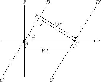
is neglected in the following analysis. In other words, the ship is treated as a point source of gravity waves. Consider Figure 11.3. This shows
a plane gravity wave generated on the surface of the water by a moving ship. The water surface corresponds to the  -
- plane. The
ship is traveling along the
  -axis, in the negative
  -direction, at the constant speed
  . Suppose that the ship's bow is initially at point
  ,
and has moved to point
  after a time interval
  . The only type of gravity wave that is continuously excited by the passage of the ship
is one that maintains a constant phase relation with respect to its bow. In fact, as we have already mentioned, the bow should always correspond to a wave maximum.
An oblique wavefront associated with such a wave is shown in the figure. Here, the wavefront
  , which initially passes through the bow at point
  , has moved
to
  after a time interval
  , such that it again passes through the bow at point
  . Of course, the wavefront propagates at the
phase velocity,
  . It follows that, in the right-angled triangle
  , the sides
  and
and  are of lengths
  and
and  , respectively,
so that
 |
(11.67) |
This, therefore, is the condition that must be satisfied in order for an obliquely propagating gravity wave to maintain a constant phase relation with respect to the ship.
Figure 11.3:
An oblique plane wave generated on the surface of the water by a moving ship.
 |
In shallow water, all gravity waves propagate at the same phase velocity: that is,
 |
(11.68) |
where  is the water depth. Hence, Equation (11.67) yields
![$\displaystyle \beta = \sin^{-1}\left[\frac{(g\,d)^{1/2}}{V}\right].$](img4015.png) |
(11.69) |
This equation can only be satisfied when
 |
(11.70) |
In other words, the ship must be traveling faster than the critical speed
 .
Moreover, if this is the case then there is only one value of
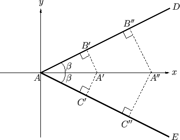
  that satisfies Equation (11.69). This implies the scenario illustrated in
Figure 11.4. Here, the ship is instantaneously at
  , and the wave maxima that it previously generated--which all
propagate obliquely, subtending a fixed angle
  with the
  -axis--have interfered constructively
to produce a single strong wave maximum
  . In fact, the wave maxima generated when the ship was at
  have travelled to
 and
and  , the wave maxima generated when the ship was at
  have travelled to
  and
and  , et cetera. We conclude
that a ship traveling over shallow water produces a V-shaped wake whose semi-angle,
  , is determined by the ship's speed.
Indeed, as is apparent from Equation (11.69), the faster the ship travels over the water, the smaller the angle
  becomes.
Shallow water wakes are especially dangerous to other vessels, and particularly destructive of the coastline, because all
of the wave energy produced by the ship is concentrated into a single large wave maximum. Note, finally, that the wake
contains no transverse waves, because, as we have already mentioned, such waves cannot keep up with a ship
traveling faster than the critical speed
 .
.
Figure 11.4:
A shallow water wake.
 |
Let us now discuss the wake generated by a ship traveling over deep water. In this case, the phase velocity of
gravity waves is
 . Thus, Equation (11.67) yields
 |
(11.71) |
It follows that in deep water any obliquely propagating gravity wave whose wave number exceeds the critical value
 |
(11.72) |
can keep up with the ship, as long as its direction of propagation is such that Equation (11.71) is satisfied. In other words, the
ship continuously excites gravity waves with a wide range of different wave numbers and propagation directions. The
wake is essentially the interference pattern generated by these waves. As is well known (Fitzpatrick 2013), an interference maximum
generated by the superposition of plane waves with a range of different wave numbers propagates at the group velocity,  .
Furthermore, as we have already seen, the group velocity of deep water gravity waves is half their phase velocity: that is,
  .
.
Figure 11.5:
Formation of an interference maximum in a deep water wake.
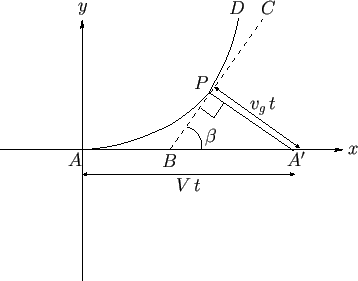 |
Consider Figure 11.5. The curve  corresponds to a particular interference maximum in the wake. Here,
  is
the ship's instantaneous position. Consider a point
  on this curve. Let
  and
and  be the coordinates of this point, relative to the
ship. The interference maximum at
  is part of the plane wavefront
  emitted some time
  earlier, when the ship was at point
  .
Let
.
Let  be the angle subtended between this wavefront and the
  -axis.
Because interference maxima propagate at the group velocity, the distance
  is equal to
  . Of course, the distance
  is
equal to
  . Simple trigonometry reveals that
Moreover,
 |
(11.75) |
because  is the tangent to the curve
  --that is, the curve
  --at point
  . It follows from Equation (11.71), and the fact that
  , that
where
 . The previous three equations can be combined to produce
which reduces to
 |
(11.79) |
This expression can be solved to give
 |
(11.80) |
where  is a constant. Hence, the locus of our interference maximum is determined parametrically by
Here, the angle  ranges
from
  to
to  .
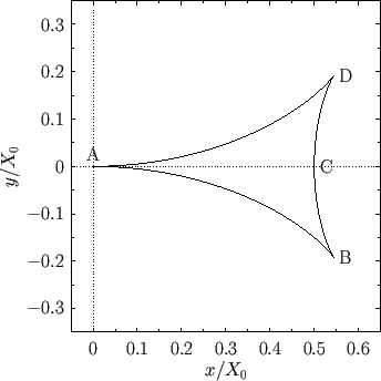
The curve specified by the previous equations is plotted in Figure 11.6. As usual,
  is the instantaneous
position of the ship. It can be seen that the interference maximum essentially consists of the transverse maximum
  , and the two radial maxima
  and
and  . As is easily demonstrated, point
  , which corresponds to
  , lies at
  ,
,  . Moreover, the
two cusps,
  and
and  , which correspond to
 , lie at
 ,
,
 .
.
Figure 11.6:
Locus of an interference maximum in a deep water wake.
 |
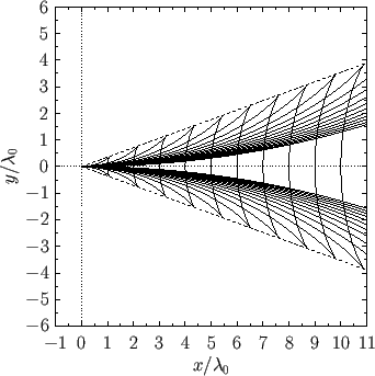
The complete interference pattern that constitutes the wake is constructed out of many different wave maximum curves of the form shown in Figure 11.6, corresponding to
many different values of the parameter  . However, these
  values must be chosen such that the wavelength of the pattern
along the
  -axis corresponds to the wavelength
 of transverse (i.e.,
  ) gravity waves whose
phase velocity matches the speed of the ship. This implies that
 , where
  is a positive integer. A complete deep water wake pattern is
shown in Figure 11.7. This pattern, which is made up of interlocking transverse and radial wave maxima, fills a wedge-shaped region--known
as a Kelvin wedge--whose semi-angle takes the value
 . This angle is independent of the ship's speed. Finally, our initial assumption that the gravity waves that form
the wake are all deep water waves is valid provided
 , which implies that
 |
(11.83) |
In other words, the ship must travel at a speed that is much less than the critical speed
 . This explains why the
wake contains transverse wave maxima.
Figure 11.7:
A deep water wake.
 |


Next: Gravity Waves in a
Up: Waves in Incompressible Fluids
Previous: Wave Drag on Ships
Richard Fitzpatrick
2016-01-22

![]() . Thus, Equation (11.67) yields
. Thus, Equation (11.67) yields

![]() corresponds to a particular interference maximum in the wake. Here,
corresponds to a particular interference maximum in the wake. Here, ![]() is
the ship's instantaneous position. Consider a point
is
the ship's instantaneous position. Consider a point ![]() on this curve. Let
on this curve. Let ![]() and
and ![]() be the coordinates of this point, relative to the
ship. The interference maximum at
be the coordinates of this point, relative to the
ship. The interference maximum at ![]() is part of the plane wavefront
is part of the plane wavefront ![]() emitted some time
emitted some time ![]() earlier, when the ship was at point
earlier, when the ship was at point ![]() .
Let
.
Let ![]() be the angle subtended between this wavefront and the
be the angle subtended between this wavefront and the ![]() -axis.
Because interference maxima propagate at the group velocity, the distance
-axis.
Because interference maxima propagate at the group velocity, the distance ![]() is equal to
is equal to ![]() . Of course, the distance
. Of course, the distance ![]() is
equal to
is
equal to ![]() . Simple trigonometry reveals that
. Simple trigonometry reveals that


![$\displaystyle =\frac{dy/d\beta}{dx/d\beta} = \frac{(1/2)\,dX/d\beta\,\sin\beta\...
...\beta-\sin^2\beta)} {dX/d\beta\,[1-(1/2)\,\sin^2\beta]-X\,\sin\beta\,\cos\beta}$](img4039.png)


![]() . However, these
. However, these ![]() values must be chosen such that the wavelength of the pattern
along the
values must be chosen such that the wavelength of the pattern
along the ![]() -axis corresponds to the wavelength
-axis corresponds to the wavelength
![]() of transverse (i.e.,
of transverse (i.e., ![]() ) gravity waves whose
phase velocity matches the speed of the ship. This implies that
) gravity waves whose
phase velocity matches the speed of the ship. This implies that
![]() , where
, where ![]() is a positive integer. A complete deep water wake pattern is
shown in Figure 11.7. This pattern, which is made up of interlocking transverse and radial wave maxima, fills a wedge-shaped region--known
as a Kelvin wedge--whose semi-angle takes the value
is a positive integer. A complete deep water wake pattern is
shown in Figure 11.7. This pattern, which is made up of interlocking transverse and radial wave maxima, fills a wedge-shaped region--known
as a Kelvin wedge--whose semi-angle takes the value
![]() . This angle is independent of the ship's speed. Finally, our initial assumption that the gravity waves that form
the wake are all deep water waves is valid provided
. This angle is independent of the ship's speed. Finally, our initial assumption that the gravity waves that form
the wake are all deep water waves is valid provided
![]() , which implies that
, which implies that