

Next: Vortex Sheets
Up: Incompressible Aerodynamics
Previous: Cylindrical Airfoils
Zhukovskii's Hypothesis
According to the previous analysis, the lift acting on a cylindrical airfoil of elliptic
cross-section, situated in a uniform, high Reynolds number wind, depends on the circulation,
 , of air about the airfoil. But,
how can we determine the value of this circulation?
Figure 9.3:
The boundary layer and wake of a streamlined airfoil. Only shaded regions posses non-zero
vorticity.
 |
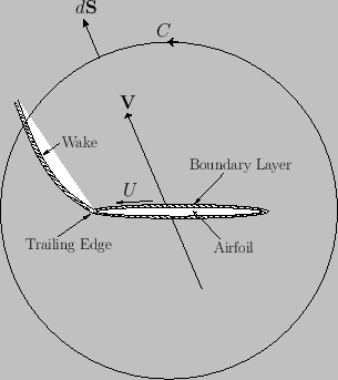
Figure 9.3 shows the boundary layer and wake of a streamlined airfoil. The boundary layer, which is localized on the surface of the
airfoil, has a vortex intensity per unit length in the  -direction equal to
  , where
  is the tangential air speed immediately above the layer. [See Equation (9.64).] Moreover, the wake is emitted by the
airfoil's trailing edge, and subsequently convected by the external air flow. (See Section 8.6.) Note that the flow is irrotational everywhere apart from inside the boundary layer and the
wake.
According to the analysis of Section 5.8, the rate of change of the circulation,
 , around some curve
  that encloses the airfoil is
equal to minus the flux of
  -directed vorticity across this curve: that is,
 |
(9.36) |
Here,  is the wind velocity,
 the wind vorticity, and
  an outward surface element (of unit depth in the
  -direction) lying on
  . We expect the vorticity flux
to be independent of the size and shape of
  , otherwise the circulation of the flow,
 , about the airfoil would not have a unique value. In the limit that
  becomes very large,
 , where
 is the incident wind velocity. Thus,
 |
(9.37) |
where  is the wind speed, and
 the vortex intensity per unit length in the wake (at the point where it crosses the curve
  ). Here, we are assuming that the
vorticity within the wake is convected by the flow, giving rise to a net flux of vorticity across
  . Because the wake is essentially an extension of
the boundary layer, it is reasonable to assume that its vortex intensity per unit length is proportional to that in the boundary layer at the airfoil's trailing edge, where the wake and boundary layer intersect. In other words,
 , where
  is the tangential velocity immediately above the trailing edge of the
airfoil, and
  is a constant. It follows that
 |
(9.38) |
According to Equation (9.27), the tangential velocity just above the surface of the airfoil is
Hence, given that the airfoil's trailing edge corresponds to
 , we obtain
![$\displaystyle U_0 = \left[\frac{{\mit\Gamma}}{\pi\,(c+\delta)}-V\,\sin\alpha\right]\left(\frac{c+\delta}{\delta}\right).$](img3336.png) |
(9.40) |
Thus, Equation (9.38) yields
 |
(9.41) |
where
![$ \widehat{\mit\Gamma}= {\mit\Gamma}/[\pi\,V\,(c+\delta)]$](img3324.png) ,
,
 , and
, and
 .
Assuming that the circulation of the flow about the airfoil is initially zero (i.e.,
 at
at  ), the
previous equation can be solved to give
![$\displaystyle \widehat{\mit\Gamma} =\sin\alpha\left[1-\exp(-\hat{t})\right].$](img3342.png) |
(9.42) |
Clearly, as
 the normalized circulation
 asymptotes to the constant value
 |
(9.43) |
The
corresponding constant value of the unnormalized circulation is
 |
(9.44) |
According to Equation (9.40), when the circulation,
 , takes the value
 the
tangential velocity at the airfoil's training edge,
  , is zero. In other words, the steady-state
circulation set up around the airfoil is such as to render its trailing edge a stagnation point of the flow. This conclusion is
known as Zhukovskii's hypothesis, after its discoverer N.E. Zhukovskii (1847-1921).
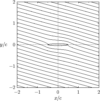
Figure:
Streamlines around a slender cylindrical airfoil of elliptic cross-section situated in a uniform, high Reynolds number wind. The parameters
for this calculation are
 ,
,
 , and
, and
 .
.
 |
Incidentally, it should be clear, from the previous discussion, that the air circulation about the airfoil is only able to change its value because
of the presence of the boundary layer, and the associated wake that trails from the airfoil's trailing edge. This follows
because the flow is irrotational everywhere except within the boundary layer and the wake. Moreover, as we have seen, a change in circulation is necessarily associated
with a net vorticity flux away from the airfoil, and such a flux cannot be carried by an irrotational wind. Thus, in the absence of the
boundary layer and the wake, the air circulation about the airfoil would be constrained to remain zero (assuming that it was initially zero), in accordance with the Kelvin
circulation theorem. (See Section 5.8.) This implies, from Equation (9.31), that zero lift would act on the airfoil, irrespective of
its shape, and irrespective
of the incident wind speed or direction. In other words, flight would be impossible. Fortunately, as long as the tangential air velocity at the trailing edge of the airfoil is non-zero, the wake that trails behind the airfoil carries a net flux of  -directed vorticity, which causes the airfoil circulation to evolve in time. This process continues until the circulation becomes such that
the tangential velocity at the airfoil's trailing edge is zero: that is, such that the trailing edge is a stagnation point. Thereafter, the
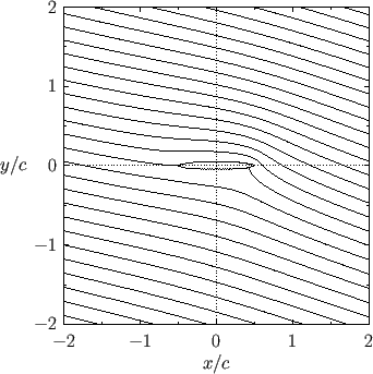
circulation remains constant (assuming that the wind speed and direction remain constant). Figures 9.4 and
9.5 show the streamlines of the flow around a slender cylindrical airfoil of elliptic cross-section situated in a uniform, high Reynolds number wind whose direction of incidence is
slightly inclined to the airfoil's major axis. In the first figure, the air circulation about the airfoil is zero. In the
second figure, the circulation is such as to make the trailing edge of the airfoil a stagnation point.
Figure:
Streamlines around a slender cylindrical airfoil of elliptic cross-section situated in a uniform, high Reynolds number wind. The parameters
for this calculation are
 ,
,
 , and
, and
 .
.
 |
According to Equations (9.31) and (9.44), when the air circulation about the airfoil has attained its steady-state value,
 ,
the lift acting on the airfoil becomes
 |
(9.45) |
The lift is positive (i.e., upward) when  (i.e., when the wind is incident on the airfoil's bottom surface),
negative (i.e., downward) when
  (i.e., when the wind is incident on the airfoil's top surface), and
zero when
  (i.e., when the wind is incident parallel to airfoil's major axis). Incidentally, the angle
  is conventionally termed
the angle of attack.
Finally, from Equations (9.35) and (9.43),
the focus of the airfoil is located a distance
 |
(9.46) |
in front of the centroid of its cross-section. In the limit that the airfoil becomes very thin (i.e.,
 ), this distance asymptotes to
  . Thus,
we conclude that
the focus of a thin airfoil, which is defined as the point of action of the lift, is located
one quarter of the way along the airfoil from its leading edge.
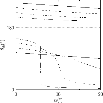
Figure:
The angular locations of the boundary layer separation points,
 , calculated as
a function of the angle of attack,
  , for a cylindrical airfoil of elliptic cross-section situated in a uniform,
high Reynolds number wind. The solid, dashed, short-dash-dotted, and long-dash-dotted curves correspond
to airfoils of ellipticity
 ,
,  ,
,  , and
, and  , respectively. The trailing edge of the airfoil
is located at
 .
.
 |
The previous analysis is premised on the assumption that there is no appreciable separation of the boundary layer from the back of the airfoil,
which implies the neglect of form drag.
We can check that this assumption is reasonable by calculating the approximate locations of the boundary layer separation points using the analysis of Section 8.10.
Let  represent arc-length along the surface of the airfoil, measured from the front stagnation point. Assuming that, in accordance
with Zhukovskii's hypothesis,
the circulation is such that
 , this stagnation point is located at
 , where
 .
[See Equation (9.49).]
It follows that
 |
(9.47) |
where
 |
(9.48) |
Moreover, from Equations (9.39) and (9.44), the tangential air speed just above the surface of the airfoil can be written
 |
(9.49) |
with
 |
(9.50) |
In addition, it can be shown that
 |
(9.51) |
where
 |
(9.52) |
According to the analysis of Section 8.10, the separation points are located at
 , where
 ,
and
,
and
 |
(9.53) |
Here,
 and
and
 . Moreover, the
  - and
- and  -coordinates of the separation
points are
 and
and
 , respectively.
Figure 9.6 shows the angular locations of the separation points, calculated as a function of the angle of attack, for cylindrical
airfoils of various different ellipticity,
  . (Note that
  has been re-expressed as an angle in the range 0
to
  .) It can be seen that for a bluff airfoil (e.g.,
 ) the angular
distance between the separation points is large, indicating the presence of a wide wake, and a high associated form drag (because the magnitude of
form drag is roughly proportional to the width of the wake).
On the other hand, for a slender airfoil (e.g.,
 ) the angular distance between the separation
points is much smaller, indicating the presence of a narrow wake, and a low associated form drag. However, in the latter case, as the
angle of attack is gradually increased from zero, there is an initial gradual increase in the angular distance between the separation points, followed
by an abrupt, and very large, increase. We would expect there to be a similar gradual increase in the form drag, followed by an
abrupt, and very large, increase. The value of the angle of attack at which this abrupt increase occurs is termed the critical angle of attack.
We conclude that the previous analysis, which neglects form drag, is valid only for slender airfoils whose angles of
attack do not exceed the critical value (which is generally only a few degrees).
Figure 9.7:
Side view of a vortex sheet.
 |


Next: Vortex Sheets
Up: Incompressible Aerodynamics
Previous: Cylindrical Airfoils
Richard Fitzpatrick
2016-01-22


![]() -direction equal to
-direction equal to ![]() , where
, where ![]() is the tangential air speed immediately above the layer. [See Equation (9.64).] Moreover, the wake is emitted by the
airfoil's trailing edge, and subsequently convected by the external air flow. (See Section 8.6.) Note that the flow is irrotational everywhere apart from inside the boundary layer and the
wake.
According to the analysis of Section 5.8, the rate of change of the circulation,
is the tangential air speed immediately above the layer. [See Equation (9.64).] Moreover, the wake is emitted by the
airfoil's trailing edge, and subsequently convected by the external air flow. (See Section 8.6.) Note that the flow is irrotational everywhere apart from inside the boundary layer and the
wake.
According to the analysis of Section 5.8, the rate of change of the circulation,
![]() , around some curve
, around some curve ![]() that encloses the airfoil is
equal to minus the flux of
that encloses the airfoil is
equal to minus the flux of ![]() -directed vorticity across this curve: that is,
-directed vorticity across this curve: that is,


![]() -directed vorticity, which causes the airfoil circulation to evolve in time. This process continues until the circulation becomes such that
the tangential velocity at the airfoil's trailing edge is zero: that is, such that the trailing edge is a stagnation point. Thereafter, the
circulation remains constant (assuming that the wind speed and direction remain constant). Figures 9.4 and
9.5 show the streamlines of the flow around a slender cylindrical airfoil of elliptic cross-section situated in a uniform, high Reynolds number wind whose direction of incidence is
slightly inclined to the airfoil's major axis. In the first figure, the air circulation about the airfoil is zero. In the
second figure, the circulation is such as to make the trailing edge of the airfoil a stagnation point.
-directed vorticity, which causes the airfoil circulation to evolve in time. This process continues until the circulation becomes such that
the tangential velocity at the airfoil's trailing edge is zero: that is, such that the trailing edge is a stagnation point. Thereafter, the
circulation remains constant (assuming that the wind speed and direction remain constant). Figures 9.4 and
9.5 show the streamlines of the flow around a slender cylindrical airfoil of elliptic cross-section situated in a uniform, high Reynolds number wind whose direction of incidence is
slightly inclined to the airfoil's major axis. In the first figure, the air circulation about the airfoil is zero. In the
second figure, the circulation is such as to make the trailing edge of the airfoil a stagnation point.

![]() ,
the lift acting on the airfoil becomes
,
the lift acting on the airfoil becomes


![]() represent arc-length along the surface of the airfoil, measured from the front stagnation point. Assuming that, in accordance
with Zhukovskii's hypothesis,
the circulation is such that
represent arc-length along the surface of the airfoil, measured from the front stagnation point. Assuming that, in accordance
with Zhukovskii's hypothesis,
the circulation is such that
![]() , this stagnation point is located at
, this stagnation point is located at
![]() , where
, where
![]() .
[See Equation (9.49).]
It follows that
.
[See Equation (9.49).]
It follows that


