


Next: The Direct Current Motor
Up: Magnetic Induction
Previous: The Direct Current Generator
The first electric dynamo was constructed in 1831 by Michael Faraday.
An electric dynamo is, of course, a device which transforms mechanical energy into
electrical energy. An electric motor, on the other hand, is a device which
transforms electrical energy into mechanical energy. In other words, an electric
motor is an electric dynamo run in reverse. It took a surprisingly long time for
scientists in the nineteenth century to realize this. In fact, the message only
really sank home after a fortuitous accident during the 1873 Vienna World Exposition.
A large hall was filled with modern gadgets. One of these gadgets,
a steam engine driven
dynamo, was producing electric power when a workman unwittingly connected the
output leads from another dynamo to the energized circuit. Almost immediately,
the latter dynamo started to whirl around at great speed. The dynamo was,
in effect, transformed into an electric motor.
An AC electric motor consists of the same basic elements as an
AC electric generator: i.e., a multi-turn coil which is free
to rotate in a constant magnetic field.
Furthermore, the rotating coil is connected to the
external circuit in just the same manner as in an AC generator: i.e., via two
slip-rings attached to metal brushes. Suppose that an external voltage
source of emf  is connected across the motor. It is assumed that
is an alternating emf, so that
is connected across the motor. It is assumed that
is an alternating emf, so that
 |
(219) |
where  is the peak voltage, and
  is the alternation frequency.
Such an emf could be obtained from an AC generator, or, more simply, from
the domestic mains supply. For the case of the mains,
is the alternation frequency.
Such an emf could be obtained from an AC generator, or, more simply, from
the domestic mains supply. For the case of the mains,
 V
and
V
and  Hz in the U.S. and Canada, whereas
 V and
V and
 Hz in Europe and Asia. The external emf drives an alternating current
 |
(220) |
around the external circuit, and through the motor. As this current flows around the
coil, the magnetic field exerts a torque on the coil, which causes it
to rotate. The motor eventually attains a steady-state in which
the rotation frequency of the coil matches the alternation frequency of the
external emf. In other words, the steady-state rotation frequency of the coil is
. Now a coil rotating in a magnetic field generates an emf  .
It is easily demonstrated that this emf acts to oppose the circulation of the
current around the coil: i.e., the induced emf acts in the opposite
direction to the external emf. For an
.
It is easily demonstrated that this emf acts to oppose the circulation of the
current around the coil: i.e., the induced emf acts in the opposite
direction to the external emf. For an  -turn coil of cross-sectional area
  rotating with frequency in a magnetic field
  , the back-emf
is given by
, the back-emf
is given by
 |
(221) |
where
 |
(222) |
and use has been made of the results
of Sect. 9.6.
Figure 43:
Circuit diagram for an AC motor connected to an external
AC emf source.
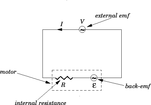 |
Figure 43 shows the circuit in question. A circle with a
wavy line inside is the conventional way of indicating an AC voltage source.
The motor is modeled as a resistor  , which represents the internal
resistance of the motor, in series with the back-emf . Of course,
the back-emf acts in the opposite direction to the external emf .
Application of Ohm's law around the circuit gives
, which represents the internal
resistance of the motor, in series with the back-emf . Of course,
the back-emf acts in the opposite direction to the external emf .
Application of Ohm's law around the circuit gives
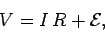 |
(223) |
or
 |
(224) |
which reduces to
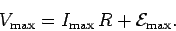 |
(225) |
The rate  at which the motor gains electrical energy from the external
circuit is given by
at which the motor gains electrical energy from the external
circuit is given by
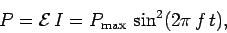 |
(226) |
where
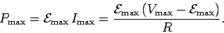 |
(227) |
By conservation of energy, is also the rate at which the motor performs
mechanical work. Note that the rate at which the motor does mechanical
work is not constant in time, but, instead, pulsates at the rotation frequency
of the coil. It is possible to construct a motor which performs work
at a more uniform rate by employing more than one coil rotating about the
same axis.
As long as
 , the rate at which the
motor performs mechanical work is positive (i.e., the motor
does useful work). However, if
, the rate at which the
motor performs mechanical work is positive (i.e., the motor
does useful work). However, if
 then the rate at which the motor performs work becomes negative. This means that
we must do mechanical work on the motor in order to keep it rotating, which
is another way of saying that the motor does not do useful work.
Clearly, in order for an AC motor to do useful work, the external emf must
be able to overcome the back-emf induced in the motor (i.e.,
).
then the rate at which the motor performs work becomes negative. This means that
we must do mechanical work on the motor in order to keep it rotating, which
is another way of saying that the motor does not do useful work.
Clearly, in order for an AC motor to do useful work, the external emf must
be able to overcome the back-emf induced in the motor (i.e.,
).
Next: The Direct Current Motor
Up: Magnetic Induction
Previous: The Direct Current Generator
Richard Fitzpatrick
2007-07-14