Next: Multi-Dimensional Waves Up: Traveling Waves Previous: Wave Propagation in Inhomogeneous Contents
 as a
superposition of two standing waves.
 as a superposition of two traveling waves propagating in
opposite directions.


 |
 |
|
 |
 |
 ,
can be written
![$\displaystyle y(x,t)=\frac{1}{2}\left[F(x-v\,t)+F(x+v\,t) + \frac{1}{v}\int_{x-v\,t}^{x+v\,t}G(x')\,dx'\right].
$](img1745.png)

 is the mean energy flux along the string due to the
wave,
 is the mean wave energy per unit length, and
  is the
phase velocity of the wave.
 occupies the region
  , and is terminated at
  .
Suppose that the current carried by the line takes the form

 ,
where
  is the amplitude of the incident signal, and
  the amplitude
of the signal reflected at the end of the line. Let the end
of the line be open circuited, such that the line is effectively terminated by an
infinite resistance. Find the relationship between
  and
and  .
Show that the current and voltage oscillate
  radians out of phase everywhere along the line. Demonstrate that there is zero net flux of
electromagnetic energy along the line.
 and
and  . Show that the current and voltage oscillate
  radians out of phase everywhere along the line. Demonstrate that there is zero net flux of
electromagnetic energy along the line.
 and
and  are connected as indicated in Figure 6.2. That is,
the outer conductors are continuous, whereas the inner wires are connected to either side of a resistor of resistance
  .
The length of the resistor is negligible compared to the wavelengths of the signals propagating down the line. Suppose that
 .
Suppose, further, that a signal is incident on the junction along the line whose impedance is
  .
.
 |
 |
|
 |
 |


 (and
(and
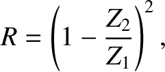
 ) then the
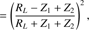
coefficient of reflection is

 ,
,  , and
, and  whose inner and
outer conductors are connected as shown in Figure 6.3. Suppose that a signal is incident on the junction along the line
whose impedance is
  .
.
![$\displaystyle R = \left[\frac{Z_2\,Z_3-Z_1\,(Z_2+Z_3)}{Z_2\,Z_3+Z_1\,(Z_2+Z_3)}\right]^{\,2},
$](img1764.png)
 and
and  are
are
 |
![$\displaystyle = \frac{4\,Z_1\,Z_2\,Z_3^{\,2}}{[Z_2\,Z_3+Z_1\,(Z_2+Z_3)]^{\,2}},$](img1766.png) |
|
 |
![$\displaystyle = \frac{4\,Z_1\,Z_2^{\,2}\,Z_3}{[Z_2\,Z_3+Z_1\,(Z_2+Z_3)]^{\,2}},$](img1768.png) |
 and
and
 .
.


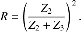
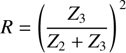
 . Suppose, however, that the signal is incident along the transmission line
whose impedance is
  .
.
 .
.
 that are connected in the manner shown in Figure 6.4.That is, the outer conductors are continuous, whereas the inner wires are connected via three identical resistors of resistance
  .
The lengths of the resistors are negligible compared to the wavelengths of the signals propagating down the lines.
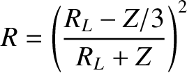
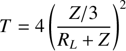

 identical transmission lines
of impedance
  meet at a common junction, and are connected via identical resistors of resistance
  .
Show that the choice


 ,in addition to an inductance per unit length
  , and a capacitance
per unit length
  . The resistance can be considered to be in series with the
inductance.
 |
 |
|
 |
 |
 and
and  are the voltage and current along the line.

 is the energy per unit length along the line, and
  the energy flux.
Give expressions for
  and
and  . What does the right-hand side of the
previous equation represent?

 .
Demonstrate that a signal propagating down the line varies
as
 |
![$\displaystyle \simeq I_0\,\cos[k\,(v\,t-x)]\,{\rm e}^{-x/\delta},\nonumber$](img1790.png) |
|
 |
![$\displaystyle \simeq Z\,I_0\,\cos[k\,(v\,t-x)-1/(k\,\delta)]\,{\rm e}^{-x/\delta},\nonumber$](img1791.png) |
 ,
,
 ,
,
 , and
, and
 . Show that
 ; that is, the
decay length of the signal is much longer than its wavelength. Estimate the
maximum useful length of a low-resistance, high-frequency, lossy transmission line.
 and perpendicular distance apart
  , where
 , is terminated by a strip of material of uniform resistance per square
meter
 . Such material is known
as spacecloth. Demonstrate that a signal sent down the line is
completely absorbed, with no reflection, by the spacecloth. Incidentally, the
resistance of a uniform strip of material is proportional to its length, and
inversely proportional to its cross-sectional area.
 kW. Show that the peak amplitude of the
electric component of solar electromagnetic radiation at the
Earth's surface is
 . Demonstrate that the
corresponding peak amplitude of the magnetic component is
 . [From Pain 1999.]
 , where
  is energy,
 is mass, and
  is the velocity of light in vacuum. This formula implies that
anything that possesses energy also has an effective mass. Use this idea to show
that an electromagnetic wave of mean intensity (energy per unit time per unit area)
 has an associated mean pressure (momentum per unit
time per unit area)
 . Hence,
estimate the mean pressure due to sunlight at the Earth's surface (assuming that the sunlight is completely absorbed).
 . The index of refraction of the glass is
  , and that
of the coating is
  . The refractive index of air can be taken to be unity.
![$\displaystyle R = \frac{(n-1)^{\,2}\,\cos^2[(\pi/2)\,(\lambda_0/\lambda)]}{4\,n+(n-1)^{\,2}\, \cos^2[(\pi/2)\,(\lambda_0/\lambda)]},
$](img1803.png)
 is the wavelength of the incident light in air.
 , and that this value remains approximately constant for light whose wavelengths lie in the visible band.
Suppose that
 , which corresponds to green light.
It follows that
  for green light. What is
  for blue light of wavelength
 , and for red light of wavelength
 ? Comment
on how effective the coating is at suppressing unwanted reflection of visible light incident
on the lens.
 . Demonstrate that the
coating also suppresses reflection from light whose frequency is
  ,
,  , et cetera, assuming that the
refractive index of the coating and the glass is frequency independent.
 -direction, and propagating in the
  -direction through an electrical
conducting medium of conductivity
  , is governed by
 |
 |
|
 |
 |
 and
and  are the electric and magnetic components
of the wave. (See Appendix C.)

 is the electromagnetic energy per unit volume, and
  the electromagnetic energy flux.
Give expressions for
  and
and  . What does the right-hand side of the
previous equation represent?
 obeys the wave-diffusion
equation

 .
.
 . Show that a wave propagating into the medium varies as
 |
![$\displaystyle \simeq E_0\,\cos[k\,(v\,t-z)]\,{\rm e}^{-z/\delta},$](img1818.png) |
|
 |
![$\displaystyle \simeq Z_0^{\,-1}\,E_0\,\cos[k\,(v\,t-z)-1/(k\,\delta)]\,{\rm e}^{-z/\delta},$](img1819.png) |
 ,
,
 , and
, and
 .
Demonstrate that
 ; that is, the wave penetrates many wavelengths into the medium.
Estimate how far a high-frequency electromagnetic wave penetrates into a low-conductivity conducting medium.
 , and the receiver the speed
  (in the same
direction). In addition, suppose that a wind of speed
  (in the same direction) is blowing from the source to the receiver. Show that if the source
emits sound whose frequency is
  in still air then the frequency recorded by the
receiver is

 is the speed of sound in still air.
Note that if the velocities of the source and receiver are the same then the wind makes no difference to
the frequency of the recorded signal. [Modified from French 1971.]