


Next: The Alternating Current Motor
Up: Magnetic Induction
Previous: The Alternating Current Generator
Most common electrical appliances (e.g., electric light-bulbs, and electric
heating elements) work fine on AC electrical power. However, there are some
situations in which DC power is preferable. For instance, small electric
motors (e.g., those which power food mixers and vacuum cleaners) work very well on AC
electricity, but very large electric motors (e.g., those
which power subway trains) generally work much better on DC electricity. Let us
investigate how DC electricity can be generated.
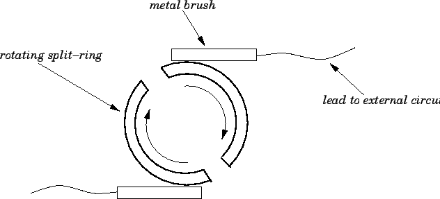
Figure 41:
A split-ring commutator.
 |
A simple DC generator consists of the same basic elements as a simple
AC generator: i.e., a multi-turn coil rotating uniformly in a magnetic
field. The main difference between a DC generator and an AC generator lies
in the manner in which the rotating coil is connected to the external circuit
containing the load. In an AC generator, both ends of the coil are connected
to separate slip-rings which co-rotate with the coil, and are connected to
the external circuit via wire brushes. In this manner, the emf
 seen by the external circuit is always the same as the emf
  generated around the rotating
coil. In a DC generator, the two ends of the coil are attached to different halves
of a single split-ring which co-rotates with the coil. The split-ring is connected
to
the external circuit by means of metal brushes--see Fig. 41.
This combination of a rotating split-ring and stationary metal brushes
is called a commutator. The purpose of the commutator is to ensure that
the emf
seen by the external circuit
is equal to the emf
generated around the rotating
coil for half the rotation period, but is equal to minus this emf for the
other half (since the connection between the external circuit and the rotating
coil is reversed by the commutator every half-period of rotation). The
positions of the metal brushes can be adjusted such that the connection between
the rotating coil and the external circuit reverses whenever the emf
generated around the coil goes through zero. In this special case,
the emf seen in the external circuit is simply
generated around the rotating
coil. In a DC generator, the two ends of the coil are attached to different halves
of a single split-ring which co-rotates with the coil. The split-ring is connected
to
the external circuit by means of metal brushes--see Fig. 41.
This combination of a rotating split-ring and stationary metal brushes
is called a commutator. The purpose of the commutator is to ensure that
the emf
seen by the external circuit
is equal to the emf
generated around the rotating
coil for half the rotation period, but is equal to minus this emf for the
other half (since the connection between the external circuit and the rotating
coil is reversed by the commutator every half-period of rotation). The
positions of the metal brushes can be adjusted such that the connection between
the rotating coil and the external circuit reverses whenever the emf
generated around the coil goes through zero. In this special case,
the emf seen in the external circuit is simply
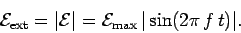 |
(218) |
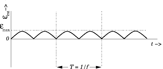
Figure 42 shows
plotted as a function of
time, according to the above formula. The variation of the emf with time is
very similar to that of an AC generator, except that whenever the AC generator
would produce a negative emf the commutator in the DC generator reverses
the polarity of the coil with respect to the external circuit, so that the negative
half of the AC signal is reversed and made positive. The result is a bumpy
direct emf which rises and falls but never changes direction. This type of
pulsating emf can be smoothed out by using more than one coil rotating about the
same axis, or by other electrical techniques, to give a good imitation of the
direct current delivered by a battery. The alternator in a car
(i.e., the DC generator which recharges the battery) is a common example
of a DC generator
of the type discussed above. Of course, in an alternator, the external torque needed to rotate
the coil is provided by the engine of the car.
Figure 42:
Emf generated in a steadily rotating DC
generator.
 |
Next: The Alternating Current Motor
Up: Magnetic Induction
Previous: The Alternating Current Generator
Richard Fitzpatrick
2007-07-14