


Next: Dielectrics
Up: Capacitance
Previous: Breakdown
As we have seen, the amount of charge which can be stored on a conductor is limited
by the electric field-strength just above its surface,
which is not allowed to exceed a certain critical value,  .
Unfortunately, the field-strength varies from point to point across the surface (unless the
surface possesses a constant radius of curvature). It is, therefore,
generally convenient
to parameterize the maximum field-strength above the surface of a conductor
in terms of the voltage difference
.
Unfortunately, the field-strength varies from point to point across the surface (unless the
surface possesses a constant radius of curvature). It is, therefore,
generally convenient
to parameterize the maximum field-strength above the surface of a conductor
in terms of the voltage difference  between the conductor and either
infinity or another conductor. The point is that , unlike the electric
field-strength, is a constant over the surface, and can, therefore, be specified unambiguously.
between the conductor and either
infinity or another conductor. The point is that , unlike the electric
field-strength, is a constant over the surface, and can, therefore, be specified unambiguously.
How do we tell the difference between a good and a
bad charge storage device? Well, a good charge storage device must be capable of
storing a large amount of charge without causing breakdown. Likewise,
a bad charge storage device is only capable of storing a small amount of
charge before breakdown occurs. Thus, if we place a charge  in a good storage device then the electric fields generated just above the surface of
the device should be comparatively weak. In other words, the voltage
should be relatively small. A convenient measure of the ability of a device
to store electric charge is its capacitance,
in a good storage device then the electric fields generated just above the surface of
the device should be comparatively weak. In other words, the voltage
should be relatively small. A convenient measure of the ability of a device
to store electric charge is its capacitance,  , which is defined as the
ratio of over :
, which is defined as the
ratio of over :
 |
(105) |
Obviously, a good charge storage device possesses a high capacitance. Note
that the capacitance of a given charge storage device is a constant
which depends on the dimensions of the device, but is independent of either
or . This follows from the linear nature of the laws of
electrostatics: i.e., if we double the charge on the device, then we double the
electric fields generated around the device, and so we double the
voltage difference between the device and (say) infinity. In other words,
 . The units of capacitance are called farads (F), and
are equivalent to coulombs per volt:
. The units of capacitance are called farads (F), and
are equivalent to coulombs per volt:
 |
(106) |
A farad is actually a pretty unwieldy
unit. In fact, most of the capacitors found in electronic circuits have capacitances in the micro-farad
range.
Probably the simplest type of capacitor is the so-called
parallel plate capacitor,
which consists of two parallel conducting plates, one carrying a charge  and the other a charge
  , separated by a distance
  . Let
. Let  be the area
of the two plates. It follows that the charge densities on the plates are
be the area
of the two plates. It follows that the charge densities on the plates are
 and
and  , respectively, where
  . Now, we have
already seen (in Sect. 4.5) that the electric field generated between
two oppositely charged parallel plates is uniform, and of magnitude
. Now, we have
already seen (in Sect. 4.5) that the electric field generated between
two oppositely charged parallel plates is uniform, and of magnitude
 . The field is directed perpendicular to the
plates, and runs from the positively to the negatively charged plate.
Note that this result is only valid if the spacing between the plates is
much less than their typical dimensions.
According to Eq. (73), the potential difference between the plates is
given by
. The field is directed perpendicular to the
plates, and runs from the positively to the negatively charged plate.
Note that this result is only valid if the spacing between the plates is
much less than their typical dimensions.
According to Eq. (73), the potential difference between the plates is
given by
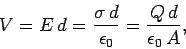 |
(107) |
where the positively charged plate is at the higher potential. It
follows from Eq. (105) that the capacitance of a parallel plate capacitor
takes the form
 |
(108) |
Note that the capacitance is proportional to the area of the plates, and
inversely proportional to their perpendicular spacing. It follows
that a good parallel plate capacitor possesses closely spaced plates of
large surface area.
Next: Dielectrics
Up: Capacitance
Previous: Breakdown
Richard Fitzpatrick
2007-07-14