In steady-state, the current ![]() flowing around the the circuit has the magnitude
flowing around the the circuit has the magnitude
| (254) |
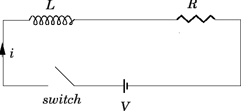
Let us now slightly modify our ![]() circuit by introducing a switch.
The new circuit is shown in Fig. 46. Suppose that the switch is initially open, but is
suddenly closed
at
circuit by introducing a switch.
The new circuit is shown in Fig. 46. Suppose that the switch is initially open, but is
suddenly closed
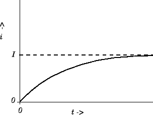
at ![]() . Obviously, we expect the instantaneous current
. Obviously, we expect the instantaneous current ![]() which flows
around the circuit, once the switch is thrown, to eventually settle
down to the steady-state
value
which flows
around the circuit, once the switch is thrown, to eventually settle
down to the steady-state
value ![]() . But, how long does this process take? Note that as the current flowing around
the circuit is building up to its final value, a non-zero back-emf is generated in the
inductor, according to Eq. (243). Thus, although the inductor does not
affect the final steady-state value of the current flowing around the circuit,
it certainly does affect how long after the switch is closed it takes
for this final current to be established.
. But, how long does this process take? Note that as the current flowing around
the circuit is building up to its final value, a non-zero back-emf is generated in the
inductor, according to Eq. (243). Thus, although the inductor does not
affect the final steady-state value of the current flowing around the circuit,
it certainly does affect how long after the switch is closed it takes
for this final current to be established.
If the instantaneous current ![]() flowing around the circuit changes by an
amount
flowing around the circuit changes by an
amount ![]() in a short time interval
in a short time interval ![]() , then the
emf generated in the inductor is given by [see Eq. (243)]
, then the
emf generated in the inductor is given by [see Eq. (243)]
| (255) |
| (256) |
Integration of Eq. (259), subject to the initial condition
(260), yields
| (261) |
| (262) |
| (263) |
Suppose that the current flowing in the circuit discussed above has settled
down to its steady-state value ![]() .
Consider what would happen
if we were to suddenly (at
.
Consider what would happen
if we were to suddenly (at ![]() , say) switch the battery out
of the circuit, and replace it by a conducting wire. Obviously,
we would expect the current to
eventually decay away to zero, since there is no longer a steady emf in the circuit
to maintain a steady current. But, how long does this process take?
, say) switch the battery out
of the circuit, and replace it by a conducting wire. Obviously,
we would expect the current to
eventually decay away to zero, since there is no longer a steady emf in the circuit
to maintain a steady current. But, how long does this process take?
Applying Ohm's law around the circuit, in the absence of the battery,
we obtain
| (264) |
Integration of Eq. (265), subject to the boundary condition (266), yields
| (267) |
We can now appreciate the significance of self inductance. The back-emf
generated in an inductor, as the current flowing through it
tries to change, effectively prevents the
current from rising (or falling) much faster than the L/R time of the
circuit. This effect is
sometimes advantageous, but is often a great nuisance.
All circuits possess some self inductance, as well as some resistance, so
all have a finite ![]() time. This means that when we power up a DC circuit, the current
does not jump up instantaneously to its steady-state value. Instead, the
rise is spread out over the
time. This means that when we power up a DC circuit, the current
does not jump up instantaneously to its steady-state value. Instead, the
rise is spread out over the ![]() time of the circuit. This is a good thing.
If the current were to rise instantaneously then extremely large
inductive electric
fields would be generated by the sudden jump in the magnetic field, leading,
inevitably, to breakdown and electric arcing. So, if there were no such thing
as self inductance then every time we switched a DC electric circuit on or off
there would be a big blue flash due to arcing between
conductors. Self inductance
can also be a bad thing. Suppose that we possess a fancy power supply, and wish
to use it to send an electric signal down a wire.
Of course, the wire will possess both resistance and inductance,
and will, therefore, have some characteristic
time of the circuit. This is a good thing.
If the current were to rise instantaneously then extremely large
inductive electric
fields would be generated by the sudden jump in the magnetic field, leading,
inevitably, to breakdown and electric arcing. So, if there were no such thing
as self inductance then every time we switched a DC electric circuit on or off
there would be a big blue flash due to arcing between
conductors. Self inductance
can also be a bad thing. Suppose that we possess a fancy power supply, and wish
to use it to send an electric signal down a wire.
Of course, the wire will possess both resistance and inductance,
and will, therefore, have some characteristic ![]() time. Suppose that we
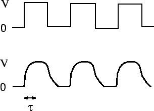
try to send a square-wave signal down the wire. Since the current in the wire
cannot rise or fall faster than the
time. Suppose that we
try to send a square-wave signal down the wire. Since the current in the wire
cannot rise or fall faster than the ![]() time, the leading and trailing edges of
the signal get smoothed out over an
time, the leading and trailing edges of
the signal get smoothed out over an ![]() time. The typical difference between
the signal fed into the wire (upper trace) and that which comes out of the
other end (lower trace) is illustrated in Fig. 48. Clearly, there is little
point in us having a fancy power supply unless we also possess a low inductance
wire, so that the signal from the power supply can be
transmitted to some load device without serious distortion.
time. The typical difference between
the signal fed into the wire (upper trace) and that which comes out of the
other end (lower trace) is illustrated in Fig. 48. Clearly, there is little
point in us having a fancy power supply unless we also possess a low inductance
wire, so that the signal from the power supply can be
transmitted to some load device without serious distortion.
 |