Next: Simple Pendulum Up: Simple Harmonic Oscillation Previous: Simple Harmonic Oscillator Equation Contents
 , connected
in series with a capacitor, of capacitance
, connected
in series with a capacitor, of capacitance  . See Figure 1.6. Such
a circuit is known as an LC circuit, for obvious reasons. Suppose that
. See Figure 1.6. Such
a circuit is known as an LC circuit, for obvious reasons. Suppose that
 is the instantaneous current flowing around the circuit.
According to
standard electrical circuit theory (Fitzpatrick 2008), the
potential drop across the inductor (in the direction of the current flow) is
is the instantaneous current flowing around the circuit.
According to
standard electrical circuit theory (Fitzpatrick 2008), the
potential drop across the inductor (in the direction of the current flow) is
 .
Again, from standard electrical circuit theory (ibid.), the potential drop across the capacitor is
.
Again, from standard electrical circuit theory (ibid.), the potential drop across the capacitor is  , where
 is the charge stored on the capacitor's positive plate. However,
because electric charge is a conserved quantity (ibid.),
the current flowing around the circuit is equal to the rate at which charge accumulates on the capacitor's
positive plate; that is,
is the charge stored on the capacitor's positive plate. However,
because electric charge is a conserved quantity (ibid.),
the current flowing around the circuit is equal to the rate at which charge accumulates on the capacitor's
positive plate; that is,
 .
.
According to Kirchhoff's second circuital law, the sum of the potential drops across the various components of a closed circuital loop is equal to zero (Grant and Philips 1975). In other words,
Dividing by, and differentiating with respect to  , we obtain
where
Comparison with Equation (1.17) reveals that Equation (1.34) is a simple harmonic oscillator equation with the associated angular oscillation frequency
, we obtain
where
Comparison with Equation (1.17) reveals that Equation (1.34) is a simple harmonic oscillator equation with the associated angular oscillation frequency
 .
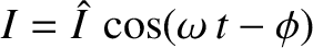
We conclude that the current in an LC circuit executes simple harmonic oscillations of the form
where
.
We conclude that the current in an LC circuit executes simple harmonic oscillations of the form
where  and
and  are constants.
According to Equation (1.33), the potential drop, , across the capacitor is minus that across the inductor, so that
 , giving
 . (See Appendix B.)
It follows that the voltage in an LC circuit oscillates at the same
frequency as the current, but with a phase shift of
. (See Appendix B.)
It follows that the voltage in an LC circuit oscillates at the same
frequency as the current, but with a phase shift of  radians. In other words, the
voltage is maximal when the current is zero, and vice versa.
The amplitude of the voltage oscillation is that of the current oscillation
multiplied by
radians. In other words, the
voltage is maximal when the current is zero, and vice versa.
The amplitude of the voltage oscillation is that of the current oscillation
multiplied by
 . Thus, we can also write
where
. Thus, we can also write
where
 is the period of the oscillation.
Comparing with Equation (1.22), we deduce that
 |
(1.39) |
 , and
, and
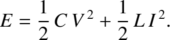
 . Thus, multiplying the
preceding expression by
. Thus, multiplying the
preceding expression by  , we obtain
The first and second terms on the right-hand side of the preceding expression can be recognized as the instantaneous energies
stored in the capacitor and the inductor, respectively (Fitzpatrick 2008). The former energy is stored in the
electric field generated when the capacitor is charged, whereas the latter is stored in the
magnetic field induced when current flows through the inductor. It follows
that the quantity
, we obtain
The first and second terms on the right-hand side of the preceding expression can be recognized as the instantaneous energies
stored in the capacitor and the inductor, respectively (Fitzpatrick 2008). The former energy is stored in the
electric field generated when the capacitor is charged, whereas the latter is stored in the
magnetic field induced when current flows through the inductor. It follows
that the quantity  in Equation (1.40) is the total energy of the circuit, and that this
energy is a conserved quantity. The oscillations
of an LC circuit can, thus, be understood as a cyclic interchange between
electric energy stored in the capacitor, and magnetic energy stored in the inductor.
in Equation (1.40) is the total energy of the circuit, and that this
energy is a conserved quantity. The oscillations
of an LC circuit can, thus, be understood as a cyclic interchange between
electric energy stored in the capacitor, and magnetic energy stored in the inductor.
Suppose that at  the capacitor is charged
to a voltage
the capacitor is charged
to a voltage  , and there is zero current flowing through the inductor. In other
words, the initial state is one in which all of the circuit energy resides in the
capacitor. The initial conditions are
, and there is zero current flowing through the inductor. In other
words, the initial state is one in which all of the circuit energy resides in the
capacitor. The initial conditions are
 and
and  .
In this case, it can be shown that the current evolves in time as
.
In this case, it can be shown that the current evolves in time as
 |
(1.41) |
the capacitor is fully discharged, and there is a current
 flowing through the inductor. In other words, the initial state is one in
which all of the circuit energy resides in the inductor. The initial
conditions are
flowing through the inductor. In other words, the initial state is one in
which all of the circuit energy resides in the inductor. The initial
conditions are
 and
and  . In this case, it can be demonstrated
that the current evolves in time as
. In this case, it can be demonstrated
that the current evolves in time as
 |
(1.42) |
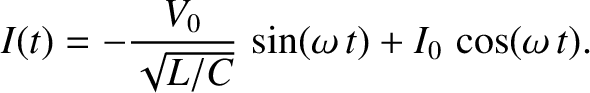
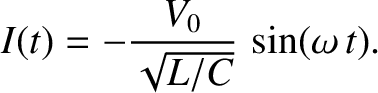
the capacitor is charged to a voltage ,
and the current flowing through the inductor is . Because the solutions
of the simple harmonic oscillator equation are superposable, it follows that the
current evolves in time as
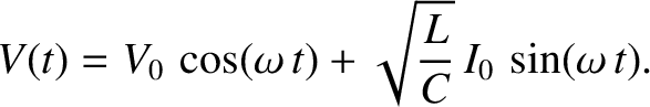
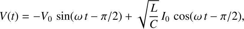
Furthermore, according to Equation (1.38), the voltage evolves in time
as
 |
(1.44) |
 and
and
 . (See Appendix B.)
![\includegraphics[width=0.75\textwidth]{Chapter01/fig1_07.eps}](img306.png) |
The instantaneous electrical power absorption by the capacitor, which can be shown to be minus the instantaneous power absorption by the inductor, is (Fitzpatrick 2008)
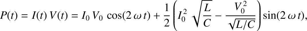 |
(1.46) |
 and
and
 . (See Appendix B.) Hence, the
average power absorption during a cycle of the oscillation,
. (See Appendix B.) Hence, the
average power absorption during a cycle of the oscillation,
 |
(1.47) |
 . In other words, any energy that the capacitor absorbs from the
circuit during one half of the oscillation cycle is returned to the circuit, without loss,
during the other. The same goes for the inductor. The time variation of the current,
. In other words, any energy that the capacitor absorbs from the
circuit during one half of the oscillation cycle is returned to the circuit, without loss,
during the other. The same goes for the inductor. The time variation of the current,  , flowing into the capacitor, the voltage drop,
  , across the capacitor, and the
power,
, across the capacitor, and the
power,  , absorbed by the capacitor, during a cycle of the oscillation is illustrated in Figure 1.7.
![\includegraphics[width=0.4\textwidth]{Chapter01/fig1_06.eps}](img287.png)