The graphical method of locating the image formed by a thin lens involves drawing light-rays emanating from key points on the object, and finding where these rays are brought to a focus by the lens. This task can be accomplished using a small number of simple rules.
Consider a converging lens. It is helpful to define two
focal points for such a lens. The first, the so-called image
focus, denoted ![]() , is defined as the point behind the
lens to which all incident light-rays parallel to the optic
axis converge after passing through the lens.
This is the same as the focal point
, is defined as the point behind the
lens to which all incident light-rays parallel to the optic
axis converge after passing through the lens.
This is the same as the focal point ![]() defined
previously. The second, the so-called object
focus, denoted
defined
previously. The second, the so-called object
focus, denoted ![]() , is defined as the position in front of
the lens for which rays emitted from a point source of light placed at
that position
would be refracted parallel to the optic axis after passing through
the lens. It is easily demonstrated that the object focus
, is defined as the position in front of
the lens for which rays emitted from a point source of light placed at
that position
would be refracted parallel to the optic axis after passing through
the lens. It is easily demonstrated that the object focus ![]() is as far in front of the optic centre
is as far in front of the optic centre ![]() of the lens as the image focus
of the lens as the image focus
![]() is behind
is behind ![]() . The distance from the optic centre to either
focus is, of course, equal to the focal length
. The distance from the optic centre to either
focus is, of course, equal to the focal length
![]() of the lens. The image produced by a converging lens can be
located using just three simple rules:
of the lens. The image produced by a converging lens can be
located using just three simple rules:
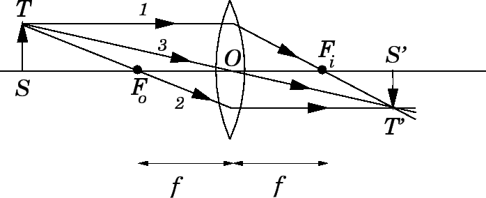
Figure 80 illustrates how the image ![]() of an object
of an object ![]() placed in front of a converging lens
is located using the above rules.
In fact, the three rays, 1-3, emanating from
the tip
placed in front of a converging lens
is located using the above rules.
In fact, the three rays, 1-3, emanating from
the tip ![]() of the object, are constructed using rules 1-3, respectively.
Note that the image is real (since light-rays actually cross), inverted, and
diminished.
of the object, are constructed using rules 1-3, respectively.
Note that the image is real (since light-rays actually cross), inverted, and
diminished.
Consider a diverging lens. It is again helpful to
define two focal points for such a lens. The image focus ![]() is
defined as the point in front of the lens from which all
incident light-rays parallel to the optic axis appear to diverge after
passing through the lens. This is the same as the focal point
is
defined as the point in front of the lens from which all
incident light-rays parallel to the optic axis appear to diverge after
passing through the lens. This is the same as the focal point ![]() defined earlier.
The object focus
defined earlier.
The object focus ![]() is
defined as the point behind the lens to which all
incident light-rays which are refracted parallel to the optic
axis after passing through the lens appear to converge. Both foci
are located a distance
is
defined as the point behind the lens to which all
incident light-rays which are refracted parallel to the optic
axis after passing through the lens appear to converge. Both foci
are located a distance ![]() from the optic centre, where
from the optic centre, where ![]() is the
focal length of the lens. The image produced by a diverging lens
can be located using the following three rules:
is the
focal length of the lens. The image produced by a diverging lens
can be located using the following three rules:
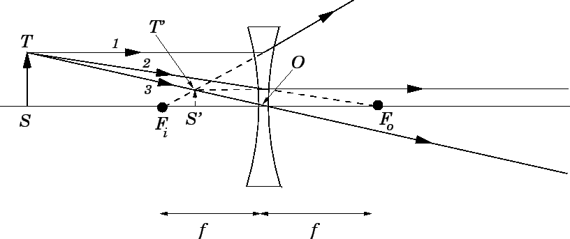
Figure 81 illustrates how the image ![]() of an object
of an object ![]() placed in front of a diverging lens
is located using the above rules.
In fact, the three rays, 1-3, emanating from
the tip
placed in front of a diverging lens
is located using the above rules.
In fact, the three rays, 1-3, emanating from
the tip ![]() of the object, are constructed using rules 1-3, respectively.
Note that the image is virtual (since light-rays do not
actually cross), upright, and
diminished.
of the object, are constructed using rules 1-3, respectively.
Note that the image is virtual (since light-rays do not
actually cross), upright, and
diminished.
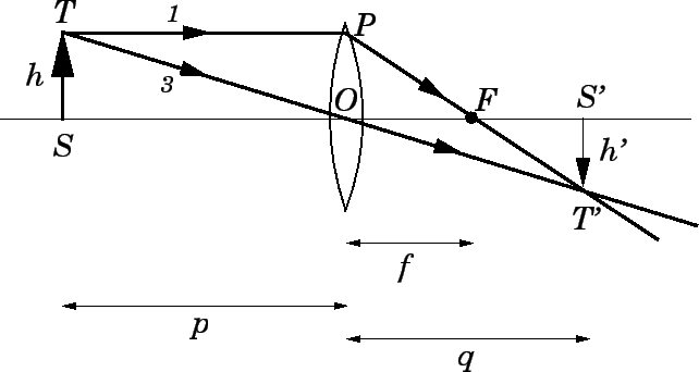
Let us now investigate the analytical method.
Consider an object of height ![]() placed a distance
placed a distance ![]() in
front of a converging lens.
Suppose that a real image of height
in
front of a converging lens.
Suppose that a real image of height ![]() is formed a distance
is formed a distance
![]() behind the lens. As is illustrated in Fig. 82,
the image can be located using rules 1 and 3,
discussed
above.
behind the lens. As is illustrated in Fig. 82,
the image can be located using rules 1 and 3,
discussed
above.
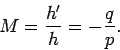
Now, the right-angled triangles ![]() and
and ![]() are similar, so
are similar, so
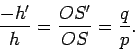 |
(363) |
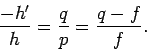
The right-angled triangles ![]() and
and ![]() are also similar, and
so
are also similar, and
so
| (365) |
 |
(366) |
Although formulae (364) and (367) were derived for the case of a real
image formed by a converging lens, they also apply to virtual images, and
to images formed by diverging lenses, provided that the following sign conventions are adopted. First of all, as we have already mentioned, the focal
length ![]() of a converging lens is positive, and the focal length of
a diverging lens is negative. Secondly, the image distance
of a converging lens is positive, and the focal length of
a diverging lens is negative. Secondly, the image distance ![]() is
positive if the image is real, and, therefore, located
behind the lens, and negative if the image is virtual,
and, therefore, located in front of the lens. It immediately follows,
from Eq. (364), that real images are always inverted, and
virtual images are always upright.
is
positive if the image is real, and, therefore, located
behind the lens, and negative if the image is virtual,
and, therefore, located in front of the lens. It immediately follows,
from Eq. (364), that real images are always inverted, and
virtual images are always upright.
Table 7 shows how the location and character of
the image formed by a converging lens depend on the location of the
object. Here, the point ![]() is located on the optic axis two focal lengths
in front of the optic centre, and the point
is located on the optic axis two focal lengths
in front of the optic centre, and the point ![]() is located on the optic
axis two focal lengths behind the optic centre. Note the almost exact analogy between the image forming properties of
a converging lens and those of a concave spherical mirror.
is located on the optic
axis two focal lengths behind the optic centre. Note the almost exact analogy between the image forming properties of
a converging lens and those of a concave spherical mirror.
Table 8 shows how the location and character of
the image formed by a diverging lens depend on the location of the
object. Note the almost exact analogy between the image forming properties of
a diverging lens and those of a convex spherical mirror.
Finally, let us reiterate the sign conventions used to determine the positions and characters of the images formed by thin lenses: