


Next: Impedance Matching
Up: Inductance
Previous: The Circuit
A transformer is a device for stepping-up, or stepping-down, the voltage of
an alternating electric
signal. Without efficient transformers, the transmission and
distribution of AC
electric power over long distances would be impossible. Figure 51
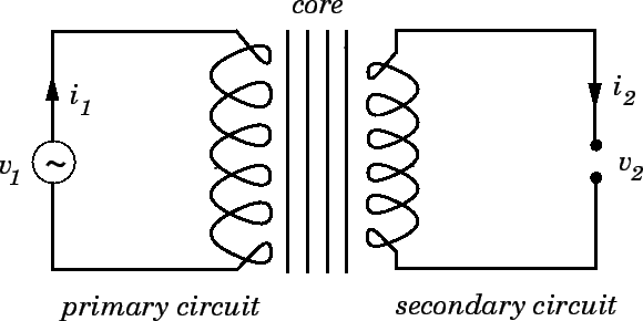
shows the circuit diagram of a typical transformer.
There are two circuits. Namely, the primary circuit, and the secondary circuit.
There is no direct electrical connection between the two circuits, but
each circuit contains a coil which links it inductively to the other circuit.
In real transformers, the two coils are wound onto the same iron core.
The purpose of the iron core is to channel the magnetic flux generated by
the current flowing around the primary coil, so that
as much of it as possible also links the
secondary coil. The common magnetic flux linking the two coils is conventionally
denoted in circuit diagrams by a number of parallel straight lines drawn between the coils.
Figure 51:
Circuit diagram of a transformer.
 |
Let us consider a particularly simple transformer in which the primary and secondary
coils are solenoids sharing the same air-filled core. Suppose that
 is the length of the core, and
  is its cross-sectional area. Let
  be
the total number of turns in the primary coil, and let
be
the total number of turns in the primary coil, and let  be the
total number of turns
in the secondary coil. Suppose that an alternating voltage
be the
total number of turns
in the secondary coil. Suppose that an alternating voltage
 |
(281) |
is fed into the primary circuit from some external AC power source. Here,
 is the peak voltage in the primary circuit, and
  is the
alternation frequency (in radians per second). The current driven around the
primary circuit is written
is the
alternation frequency (in radians per second). The current driven around the
primary circuit is written
 |
(282) |
where  is the peak current. This current generates a
changing magnetic flux,
in the core of the solenoid, which links the secondary coil, and, thereby,
inductively generates the alternating emf
is the peak current. This current generates a
changing magnetic flux,
in the core of the solenoid, which links the secondary coil, and, thereby,
inductively generates the alternating emf
 |
(283) |
in the secondary circuit, where  is the peak voltage. Suppose that this
emf drives an alternating current
is the peak voltage. Suppose that this
emf drives an alternating current
 |
(284) |
around the secondary circuit, where  is the peak current.
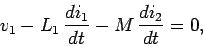
The circuit equation for the primary circuit is written
 |
(285) |
assuming that there is negligible resistance in this circuit. The first term
in the above equation is the externally generated emf. The second term is
the back-emf due to the self inductance  of the primary coil. The
final term is the emf due to the mutual inductance
of the primary coil. The
final term is the emf due to the mutual inductance  of the primary
and secondary coils. In the absence of any significant resistance in the primary
circuit, these three emfs must add up to zero. Equations (281), (282),
(284), and (285) can be combined to give
of the primary
and secondary coils. In the absence of any significant resistance in the primary
circuit, these three emfs must add up to zero. Equations (281), (282),
(284), and (285) can be combined to give
 |
(286) |
since
 |
(287) |
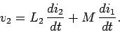
The alternating emf generated in the secondary circuit consists of the
emf generated by the self inductance  of the secondary coil, plus the
emf generated by the mutual inductance of the primary and secondary coils.
Thus,
of the secondary coil, plus the
emf generated by the mutual inductance of the primary and secondary coils.
Thus,
 |
(288) |
Equations (282), (283),
(284), (287), and (288) yield
 |
(289) |
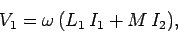
Now, the instantaneous power output of the external AC power source which drives the
primary circuit is
 |
(290) |
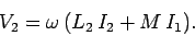
Likewise, the instantaneous electrical energy per unit time transfered inductively from the
primary to the secondary circuit is
 |
(291) |
If resistive losses in the primary
and secondary circuits are negligible, as is assumed to be the case, then,
by energy conservation, these
two powers must equal one another at all times. Thus,
 |
(292) |
which easily reduces to
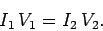 |
(293) |
Equations (286), (289), and (293) yield
 |
(294) |
which gives
 |
(295) |
and, hence,
 |
(296) |
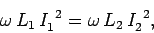
Equations (293) and (296) can be combined to give
 |
(297) |
Note that, although the mutual inductance of the two coils is
entirely responsible for the transfer of
energy between the primary and secondary circuits, it is the self inductances
of the two coils which determine the ratio of the peak voltages and
peak currents in these circuits.
Now, from Sect. 10.2, the self inductances of the primary and
secondary coils are given by
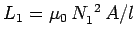 and
and
 , respectively. It follows
that
, respectively. It follows
that
 |
(298) |
and, hence, that
 |
(299) |
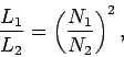
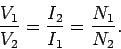
In other words, the ratio of the peak voltages and peak currents
in the primary and secondary circuits is determined by the ratio of
the number of turns in the primary and secondary coils. This latter ratio
is usually called the turns-ratio of the transformer. If
the secondary coil contains more turns than the primary coil then the
peak voltage in the secondary circuit exceeds that in the primary circuit.
This type of transformer is called a step-up transformer, because
it steps up the voltage of an AC signal. Note that in a step-up
transformer the peak current in the secondary
circuit is less than the peak current in the primary circuit (as must be the case if energy is to be conserved). Thus,
a step-up transformer actually steps down the current. Likewise,
if the secondary coil contains less turns than the primary coil
then the peak voltage in the secondary circuit is less than that
in the primary circuit. This type of transformer is called a step-down
transformer. Note that a step-down transformer actually steps up the
current (i.e., the peak current in the secondary circuit
exceeds that in the primary circuit).
AC electricity is generated in power stations at a fairly low peak voltage
(i.e., something like 440V), and is consumed by the domestic
user at a peak voltage of 110V (in the U.S.). However, AC electricity
is transmitted from the power station to the location where it is consumed
at a very high peak voltage (typically 50kV). In fact, as soon as an AC signal
comes out of a generator in a power station it is fed into a step-up
transformer which boosts its peak voltage from a few hundred volts to many tens
of kilovolts. The output from the step-up transformer is fed into a
high tension transmission line, which typically transports the electricity over
many tens of kilometers, and, once the electricity has reached its
point of consumption, it is fed through a series of step-down transformers
until, by the time it emerges from a domestic power socket, its peak voltage is
only 110V. But, if AC electricity is both generated and consumed at
comparatively low peak voltages, why go to the trouble of
stepping up the peak voltage to a very high value at the
power station, and then stepping down the voltage again once the electricity
has reached its point of consumption? Why not generate, transmit, and
distribute the electricity at a peak voltage of 110V?
Well, consider an electric
power line which transmits a peak electric power  between a power station
and a city. We can think of , which
depends on the number of consumers in the city, and the nature of the
electrical devices which they operate, as essentially a fixed number.
Suppose that
between a power station
and a city. We can think of , which
depends on the number of consumers in the city, and the nature of the
electrical devices which they operate, as essentially a fixed number.
Suppose that  and
and  are the peak voltage and peak current
of the AC signal transmitted along the line,
respectively. We can think of these numbers as being variable, since we can change
them using a transformer. However, since
are the peak voltage and peak current
of the AC signal transmitted along the line,
respectively. We can think of these numbers as being variable, since we can change
them using a transformer. However, since  , the product of the peak
voltage and the peak current must remain constant. Suppose that the resistance
of the line is
, the product of the peak
voltage and the peak current must remain constant. Suppose that the resistance
of the line is  . The peak rate at which electrical energy is lost due
to ohmic heating in the line is
. The peak rate at which electrical energy is lost due
to ohmic heating in the line is  , which can be written
 |
(300) |
Thus, if the power transmitted down the line is a fixed quantity,
as is the resistance of the line, then the
power lost in the line due to ohmic heating varies like the inverse square
of
the peak voltage in the line. It turns out that even at very high voltages,
such as 50kV, the ohmic power losses in
transmission lines which run over tens of kilometers
can amount to up to 20% of the transmitted power. It can readily be
appreciated that if an attempt were made to transmit AC electric power
at a peak voltage of 110V then the ohmic losses would be so severe that virtually none of
the power would reach its destination. Thus, it is only possible to generate
electric power at a central location, transmit it over large distances,
and then distribute it at its point of consumption, if the transmission
is performed at a very high peak voltages (the higher, the better). Transformers
play a vital role in this process because they allow us to step-up
and step-down the voltage of an AC electric signal
very efficiently (a well-designed
transformer typically has a power loss which is only a few percent of the
total power flowing through it).
Of course, transformers do not work for DC electricity, because the
magnetic flux generated by the primary coil does not vary in time,
and, therefore, does not induce an emf in the secondary coil.
In fact, there is no efficient method of stepping-up or
stepping-down the voltage of a DC electric signal. Thus, it is
impossible to efficiently transmit DC electric power over larger distances.
This is the main reason why
commercially generated electricity is AC, rather than DC.
Next: Impedance Matching
Up: Inductance
Previous: The Circuit
Richard Fitzpatrick
2007-07-14