


Next: Self Inductance
Up: Inductance
Previous: Inductance
Figure 45:
Two inductively coupled circuits.
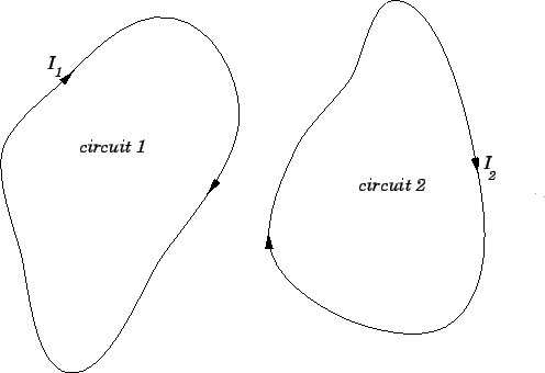 |
Consider two arbitrary conducting circuits, labelled 1 and 2. Suppose
that  is the instantaneous current flowing around circuit 1. This current
generates a magnetic field
is the instantaneous current flowing around circuit 1. This current
generates a magnetic field  which links the second circuit, giving
rise to a magnetic flux
which links the second circuit, giving
rise to a magnetic flux
 through that circuit.
If the current doubles, then the magnetic field doubles
in strength at all points in space, so the magnetic flux
through the second circuit also doubles. This conclusion follows from the
linearity of the laws of magnetostatics, plus the definition of
magnetic flux. Furthermore, it is obvious that the flux through the
second circuit is zero whenever the current flowing around the first circuit
is zero. It follows that the flux
through the second
circuit is directly proportional to the current flowing around the
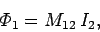
first circuit. Hence, we can write
through that circuit.
If the current doubles, then the magnetic field doubles
in strength at all points in space, so the magnetic flux
through the second circuit also doubles. This conclusion follows from the
linearity of the laws of magnetostatics, plus the definition of
magnetic flux. Furthermore, it is obvious that the flux through the
second circuit is zero whenever the current flowing around the first circuit
is zero. It follows that the flux
through the second
circuit is directly proportional to the current flowing around the
first circuit. Hence, we can write
 |
(231) |
where the constant of proportionality  is called the mutual
inductance of circuit 2 with respect to circuit 1. Similarly, the flux
is called the mutual
inductance of circuit 2 with respect to circuit 1. Similarly, the flux
 through the first circuit due to the instantaneous
current
through the first circuit due to the instantaneous
current  flowing around the second circuit is directly proportional to
that current, so we can write
flowing around the second circuit is directly proportional to
that current, so we can write
 |
(232) |
where  is the mutual
inductance of circuit 1 with respect to circuit 2. It is possible to demonstrate
mathematically that
is the mutual
inductance of circuit 1 with respect to circuit 2. It is possible to demonstrate
mathematically that
 . In other words, the flux linking
circuit 2 when a certain current flows around circuit 1 is exactly the same
as the flux linking circuit 1 when the same current flows around circuit
2. This is true irrespective of the size, number of turns,
relative position, and relative
orientation of the two circuits. Because of this, we can write
. In other words, the flux linking
circuit 2 when a certain current flows around circuit 1 is exactly the same
as the flux linking circuit 1 when the same current flows around circuit
2. This is true irrespective of the size, number of turns,
relative position, and relative
orientation of the two circuits. Because of this, we can write
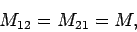 |
(233) |
where  is termed the mutual inductance of the two circuits. Note that
is a purely geometric quantity, depending only on the size, number of turns,
relative position, and relative
orientation of the two circuits. The SI units of mutual inductance
are called Henries (H). One henry is equivalent to a volt-second
per ampere:
is termed the mutual inductance of the two circuits. Note that
is a purely geometric quantity, depending only on the size, number of turns,
relative position, and relative
orientation of the two circuits. The SI units of mutual inductance
are called Henries (H). One henry is equivalent to a volt-second
per ampere:
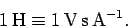 |
(234) |
It turns out that a henry is a rather unwieldy unit. The mutual inductances of
the circuits typically encountered in laboratory experiments
are measured in
milli-henries.
Suppose that the current flowing around circuit 1 changes by an amount
 in a time interval
  . It follows from
Eqs. (231) and (233) that the flux linking circuit 2 changes by an amount
. It follows from
Eqs. (231) and (233) that the flux linking circuit 2 changes by an amount
 in the same time interval.
According to Faraday's law, an emf
in the same time interval.
According to Faraday's law, an emf
 |
(235) |
is generated around the second circuit due to the changing magnetic flux
linking that circuit. Since,
,
this emf can also be written
 |
(236) |
Thus, the emf generated around the second circuit due to
the current flowing around the first circuit is directly proportional
to the rate at which that current changes.
Likewise, if the current flowing around the second circuit changes by an
amount  in a time interval then
the emf generated around the first circuit is
in a time interval then
the emf generated around the first circuit is
 |
(237) |
Note that there is no direct physical coupling between the two circuits. The coupling
is due entirely to the magnetic field generated by the currents flowing around the
circuits.
As a simple example, suppose that two insulated wires are wound on the
same cylindrical former, so as to form two solenoids sharing a common
air-filled core. Let  be the length of the core,
  the cross-sectional
area of the core,
the cross-sectional
area of the core,  the number of times the first wire is
wound around the core, and
the number of times the first wire is
wound around the core, and  the number of times the second wire is
wound around the core. If a current flows around the first
wire then a uniform axial magnetic field of strength
the number of times the second wire is
wound around the core. If a current flows around the first
wire then a uniform axial magnetic field of strength
 is generated in the core (see Sect. 8.8). The magnetic
field in the region outside the core is of negligible
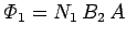
magnitude. The flux linking a single turn of the second wire is
is generated in the core (see Sect. 8.8). The magnetic
field in the region outside the core is of negligible
magnitude. The flux linking a single turn of the second wire is  . Thus,
the flux linking all turns of the second wire is
. Thus,
the flux linking all turns of the second wire is
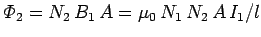 . From Eq. (231), the mutual
inductance of the second wire with respect to the first is
. From Eq. (231), the mutual
inductance of the second wire with respect to the first is
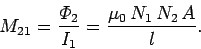 |
(238) |
Now, the flux linking the second wire when a current flows in the
first wire is
 , where
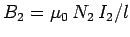 is the associated magnetic field generated in the core.
It follows from Eq. (232) that the mutual inductance of the first
wire with respect to the second is
is the associated magnetic field generated in the core.
It follows from Eq. (232) that the mutual inductance of the first
wire with respect to the second is
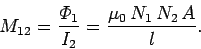 |
(239) |
Note that
 , in accordance with Eq. (233). Thus,
the mutual inductance
of the two wires is given by
, in accordance with Eq. (233). Thus,
the mutual inductance
of the two wires is given by
 |
(240) |
As described previously, is a geometric quantity depending on
the dimensions of the core, and the manner in which the two wires are
wound around the core, but not on the actual currents flowing through
the wires.
Next: Self Inductance
Up: Inductance
Previous: Inductance
Richard Fitzpatrick
2007-07-14